Step 12: Create the Display Cable (…while the glue cures…)
Parts used:
Your backlit 20x4 LCD display (see Step 5 for the one I used) with a proper datasheet.
16 pin flat ribbon cable (e.g. from AVI Showtech, but every electronics shop should carry this)
16 pin female IDC connector (buy two or three to be on the safe side, e.g. from AVI Showtech, but every electronics shop should carry this)
A screw clamp, a bench vise or a pipe wrench
A cutting knife
16 pin DIL-header or 2x8 pin SIL-header for connection testing (e.g. from AVI Showtech, but every electronics shop should carry this)
A multimeter/conductivity beeper for connection testing
A piece of transparent tape (e.g. tesa tape)
A few small cable binders
Electric isolation tape (standard material, at least 1cm width)
Description:
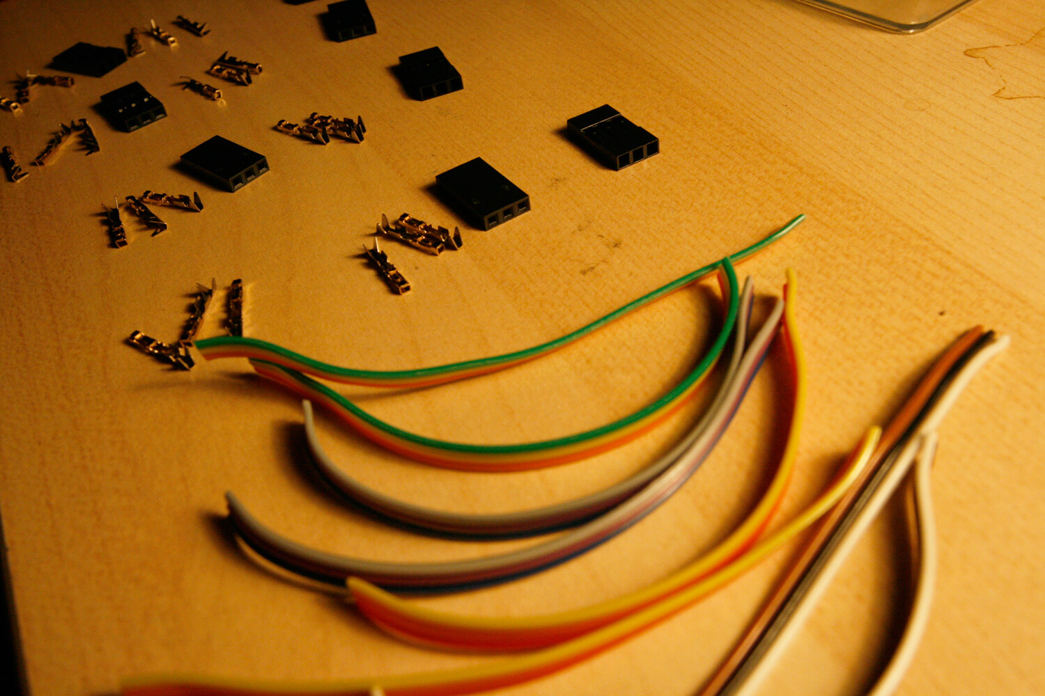
* Press the IDC connector onto the end of the ribbon cable as follows (if you have never done this before, it is good to have a few spare connectors, so you can experiment):
* Disconnect the top part of the connector.
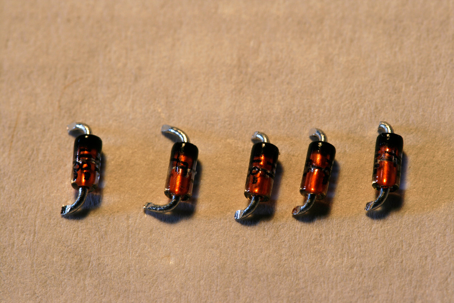
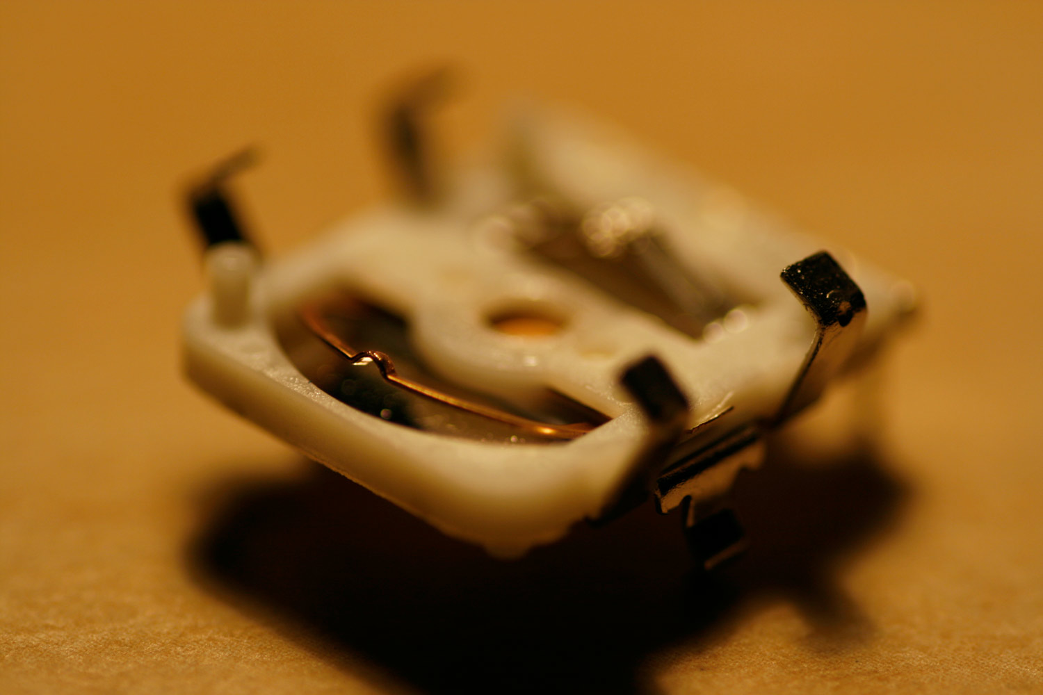
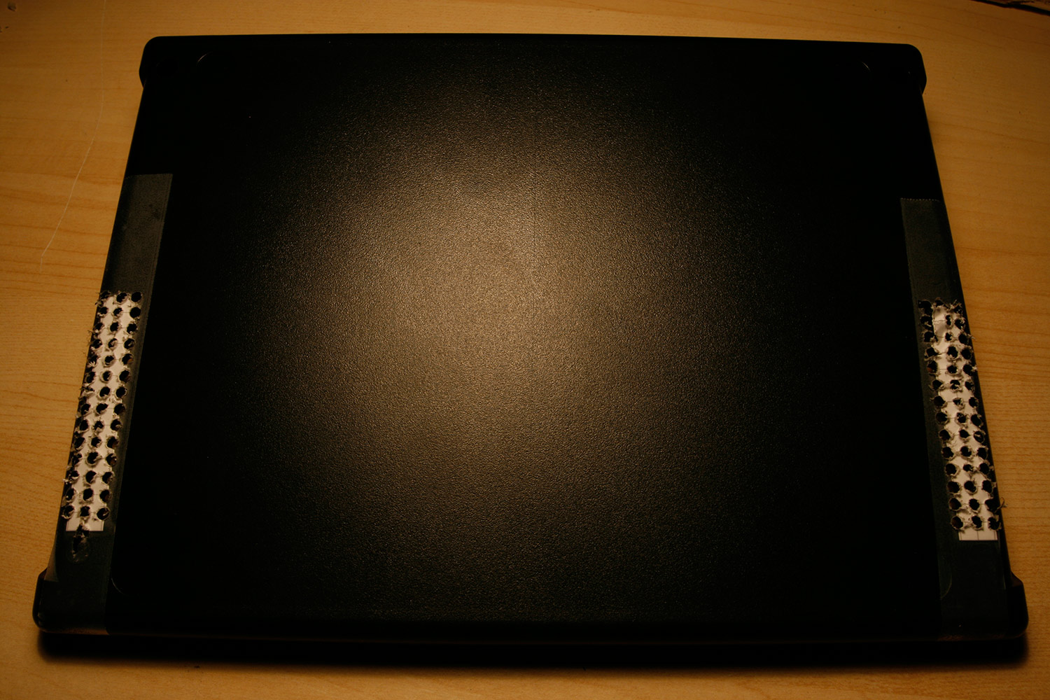
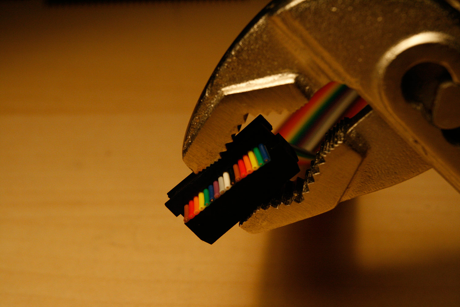
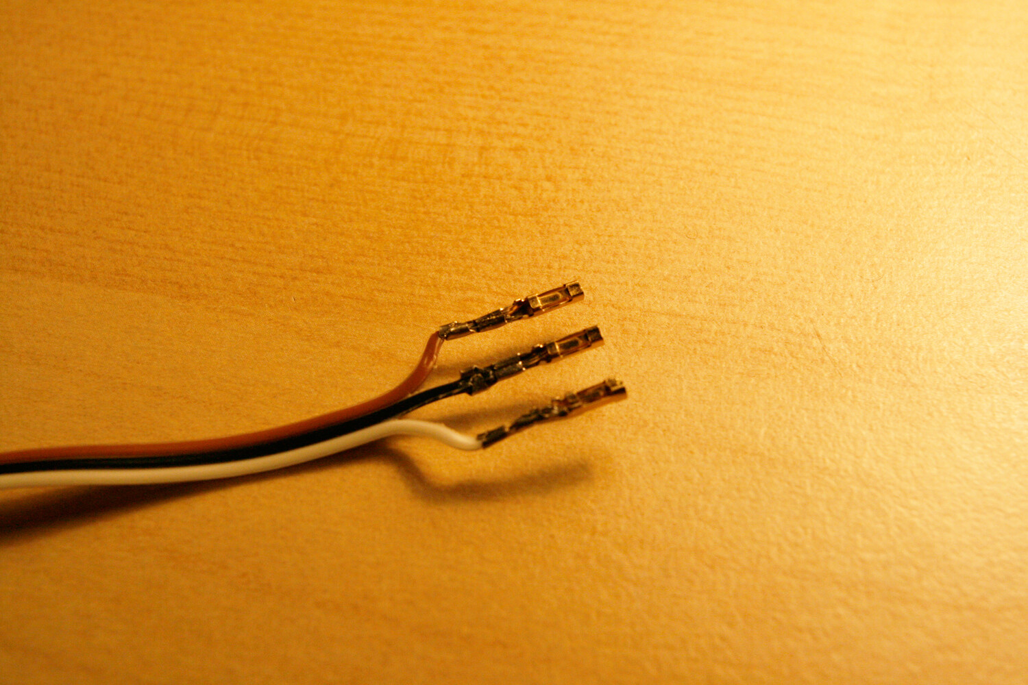
* Align the ribbon cable, so that every lead is cladded by one press-to-cut connector (photo 1)
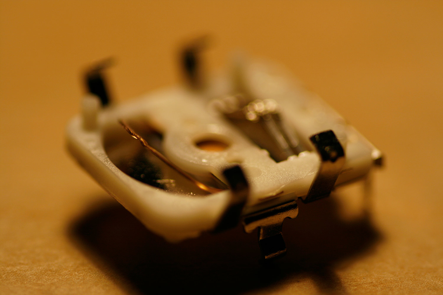
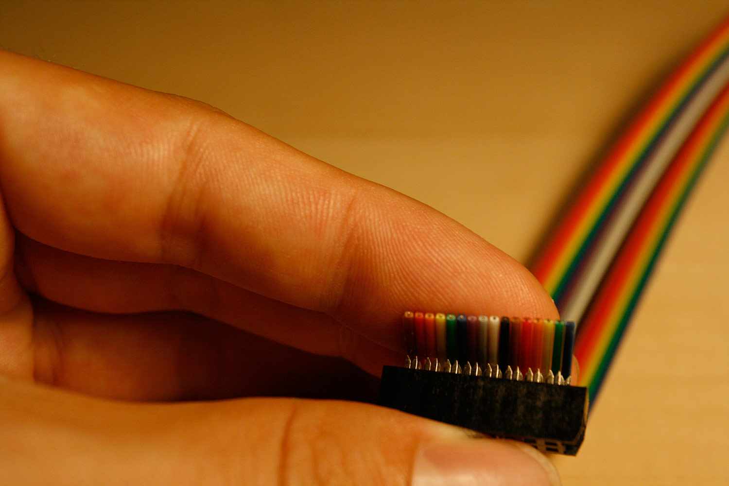
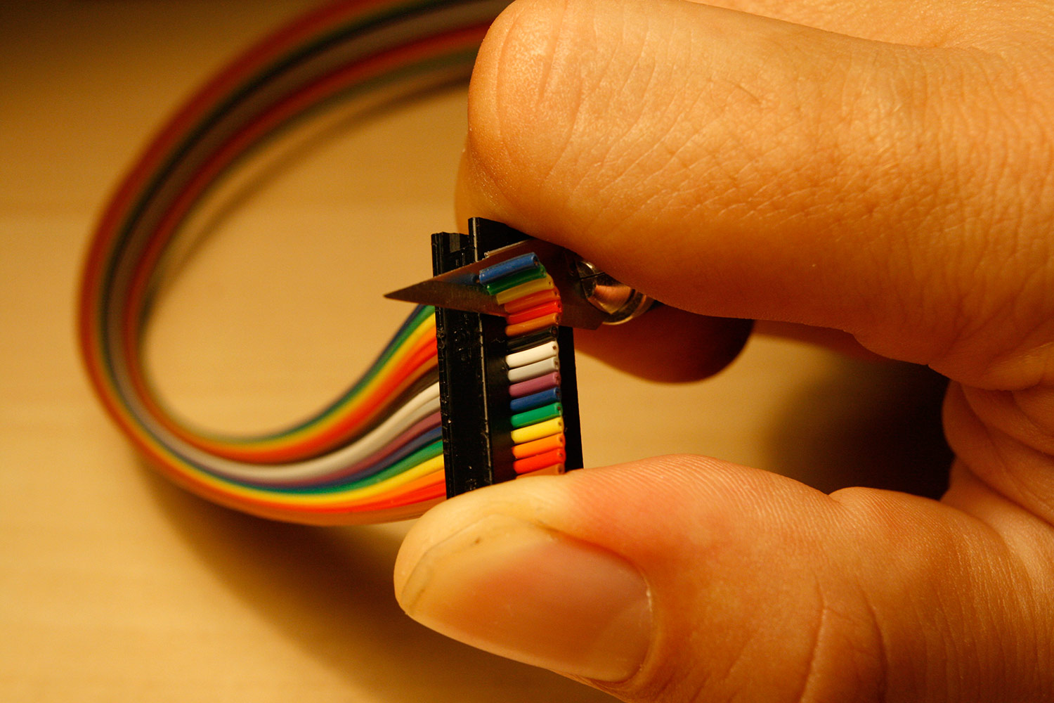
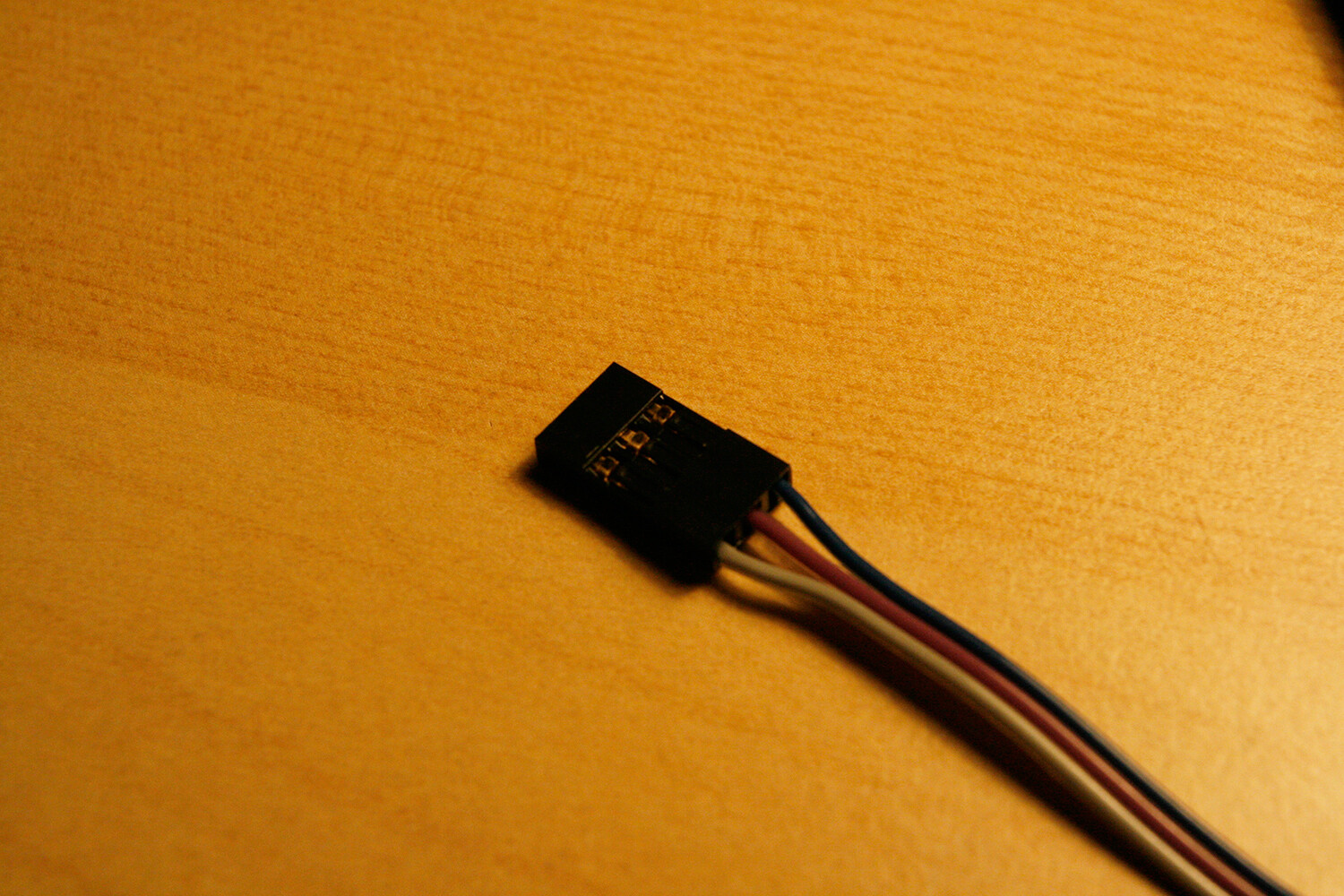
* The connector has an arrow or a marking for the first pin, make sure it is the aligned to the right, while the cable points upwards (photo 2). This is how it will be connected to the base board.
* Reattach the connector top. Now apply gentle but increasing parallel pressure to the top and bottom of the connector until it is fastened. It is easiest to do this with a screw clamp or a bench vise, but you can also use a pipe wrench (photo 3).
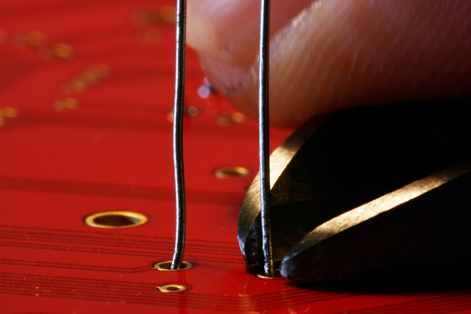
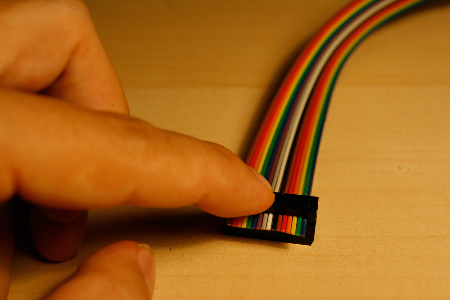
* After you have pressed the connector, cut off the remainig cable with a knife, straight at the connector (photo 4).
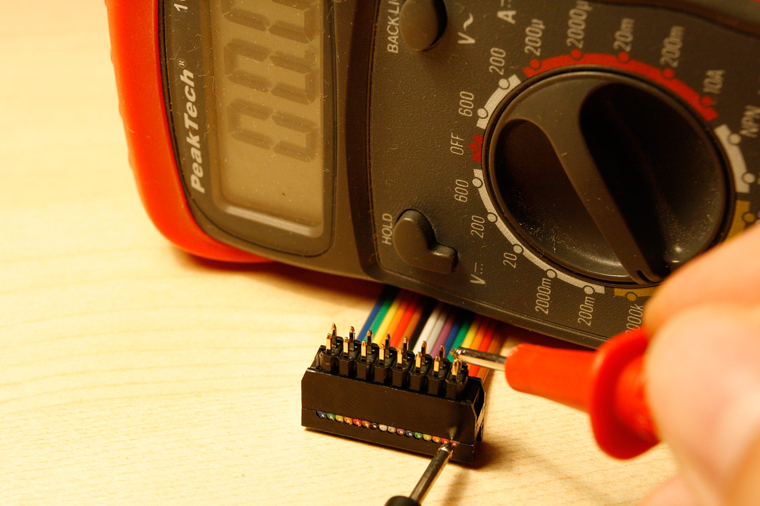
* Let´s test the connector by using your multimeter (set mode to “resistance”, when the displayed value is zero, there is a valid electrical connection) or your connection beeper. Insert the connector to a spare piece of DIL header (or two SIL headers). Now press one probe of your multimeter/connection tester to the cable end at the connector and the other probe to the corresponding DIL Header pin (photo 5). Check for connectivity. Now move the probe, that is pressed to the leads at the connector to the two neighboring leads (left and right) to check, that there is NO connectivity. Test all connector pins. If your connectivity is not well, just cut the cable end including the damaged connector off and try again with a new connector.
* Do not attach the connector strain relief, which we would normally use, if there was more space within the case.
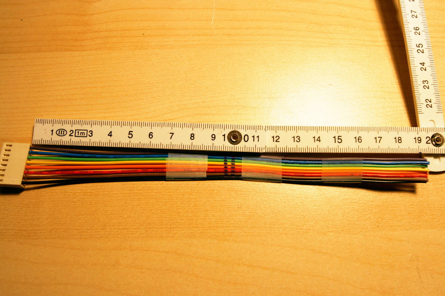
* Cut the ribbon cable to 25 centimeters of length. You can use old scissors to obtain a straight cut.
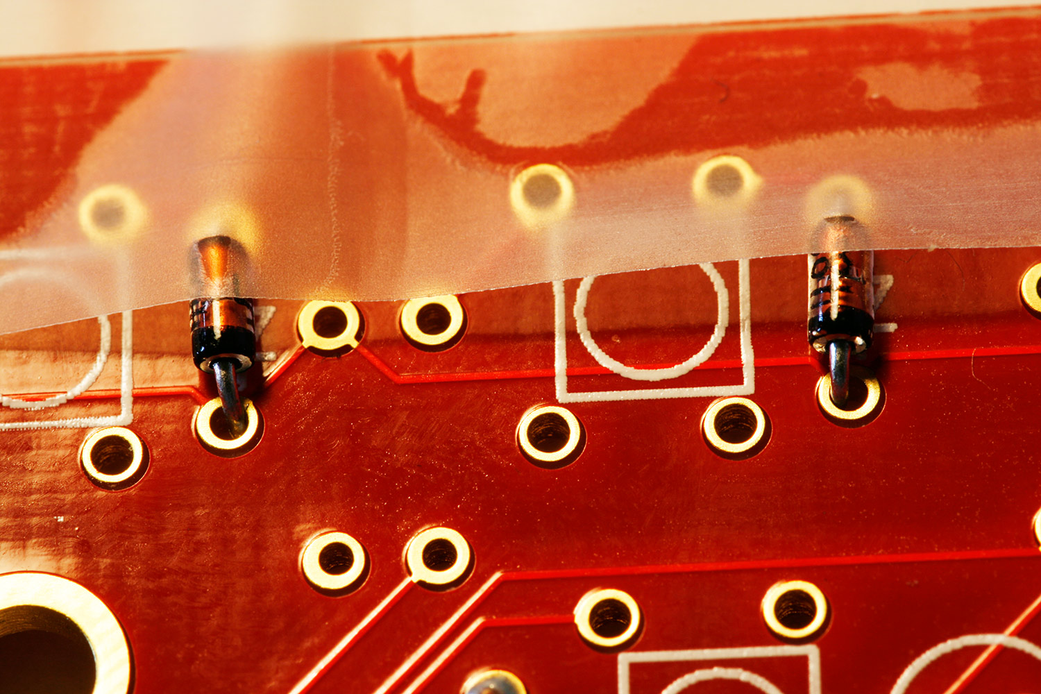
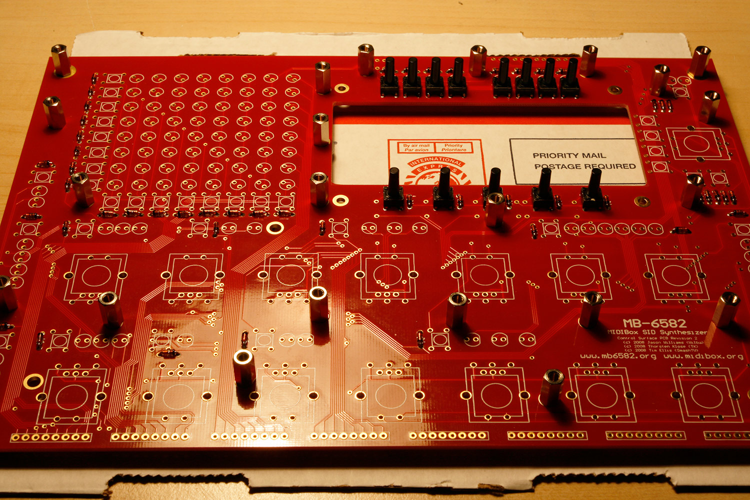
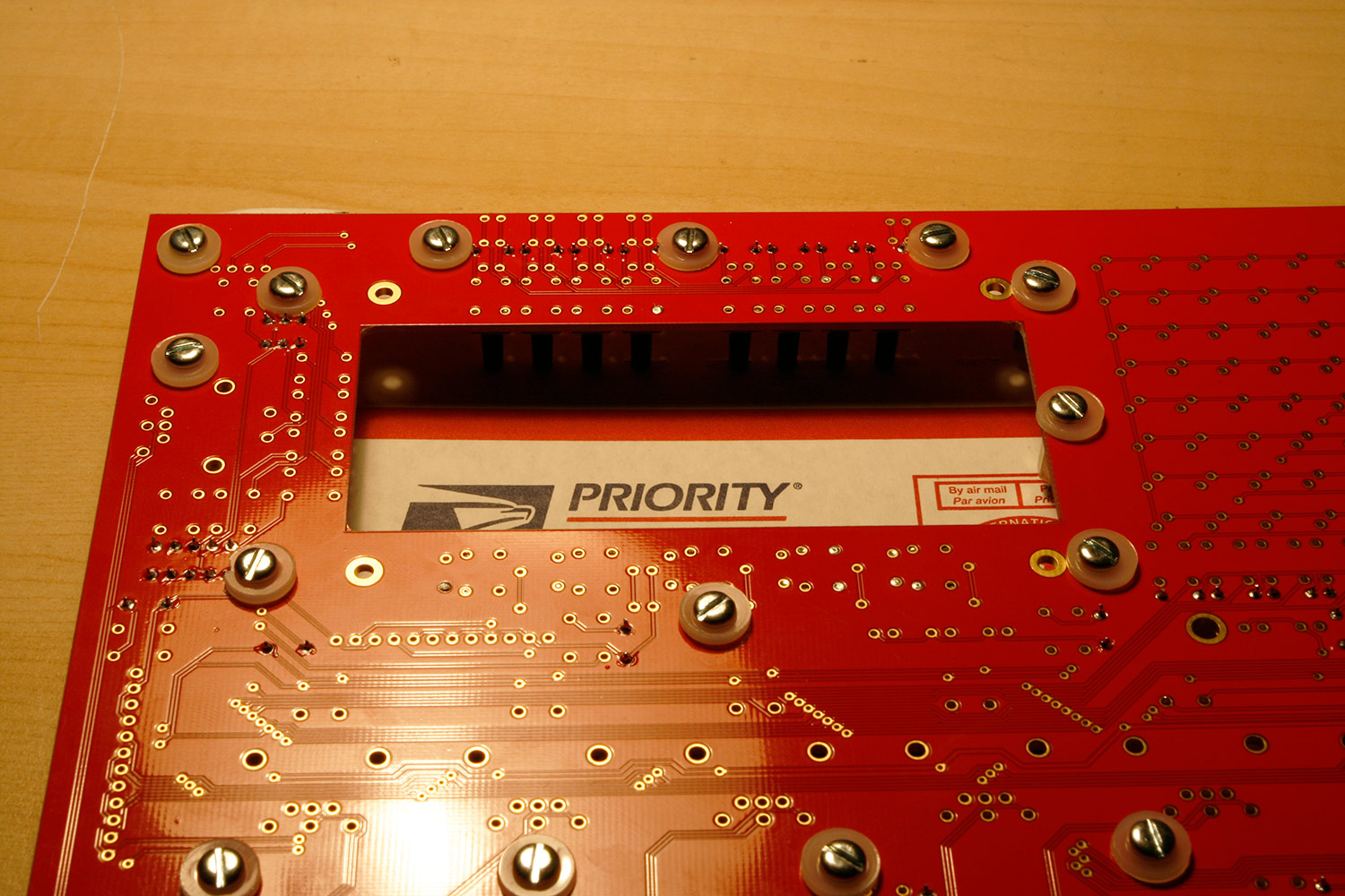
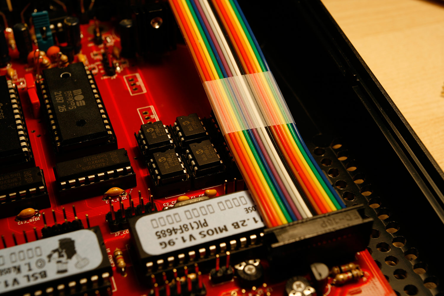
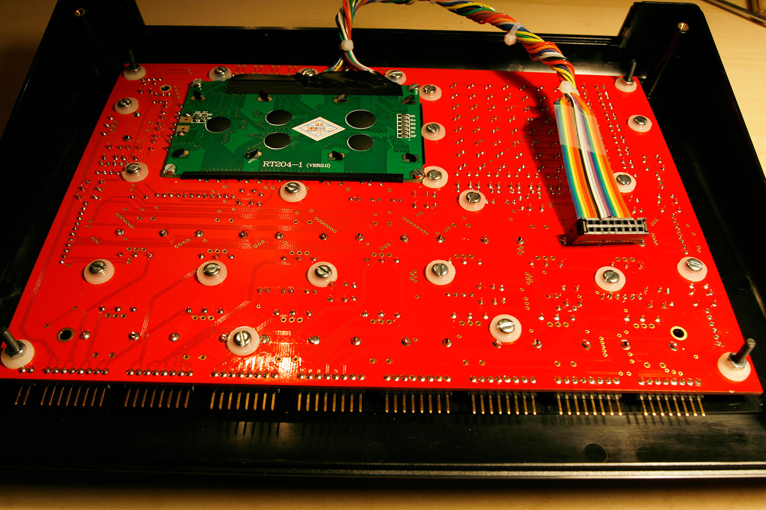
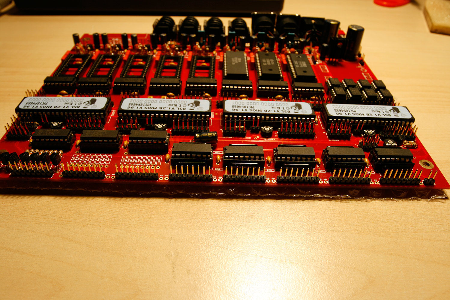
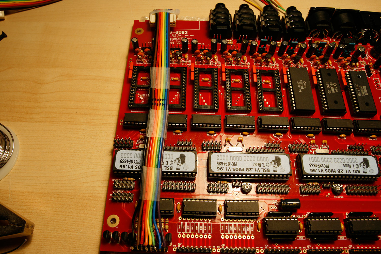
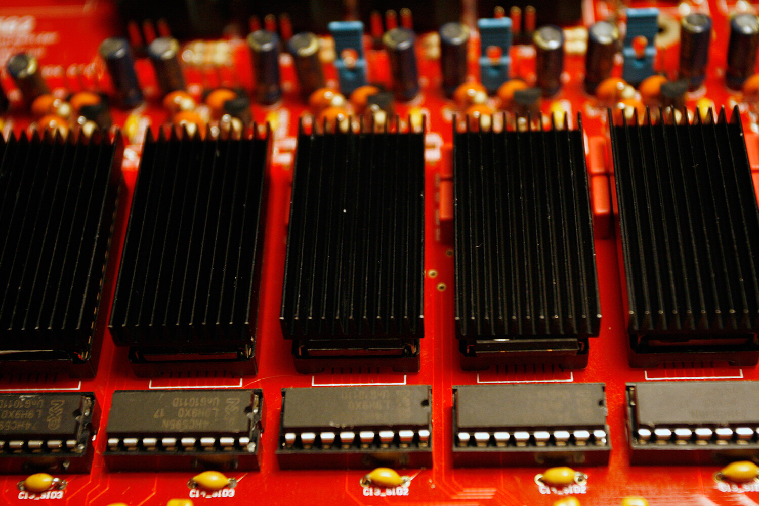
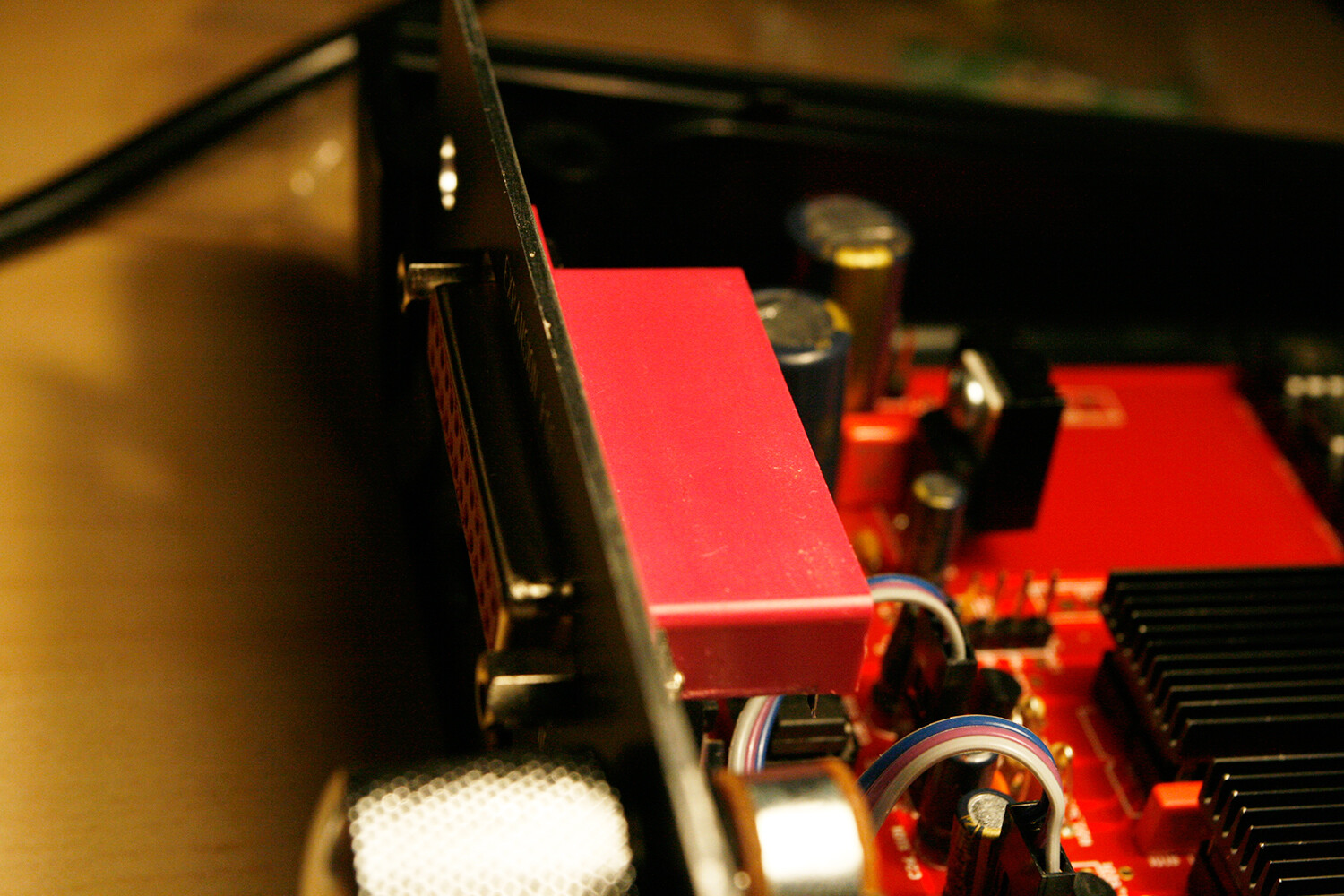
* Test-insert the connector to your base board. Now attach a piece of transparent tape to the ribbon wire just above the bank stick ics. We will splice the cable to a round cable up to this point. The tape prevents further accidental splicing (photo 6).
- phase one completed, lets connect that thing…

* Obtain the datasheet of your LCD. A google search for “<lcdname> datasheet” is helpful if you do not have a printed one. And your vendor should have one, for sure.
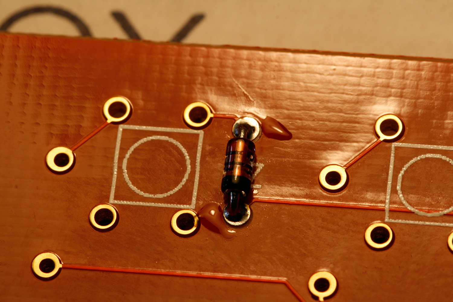
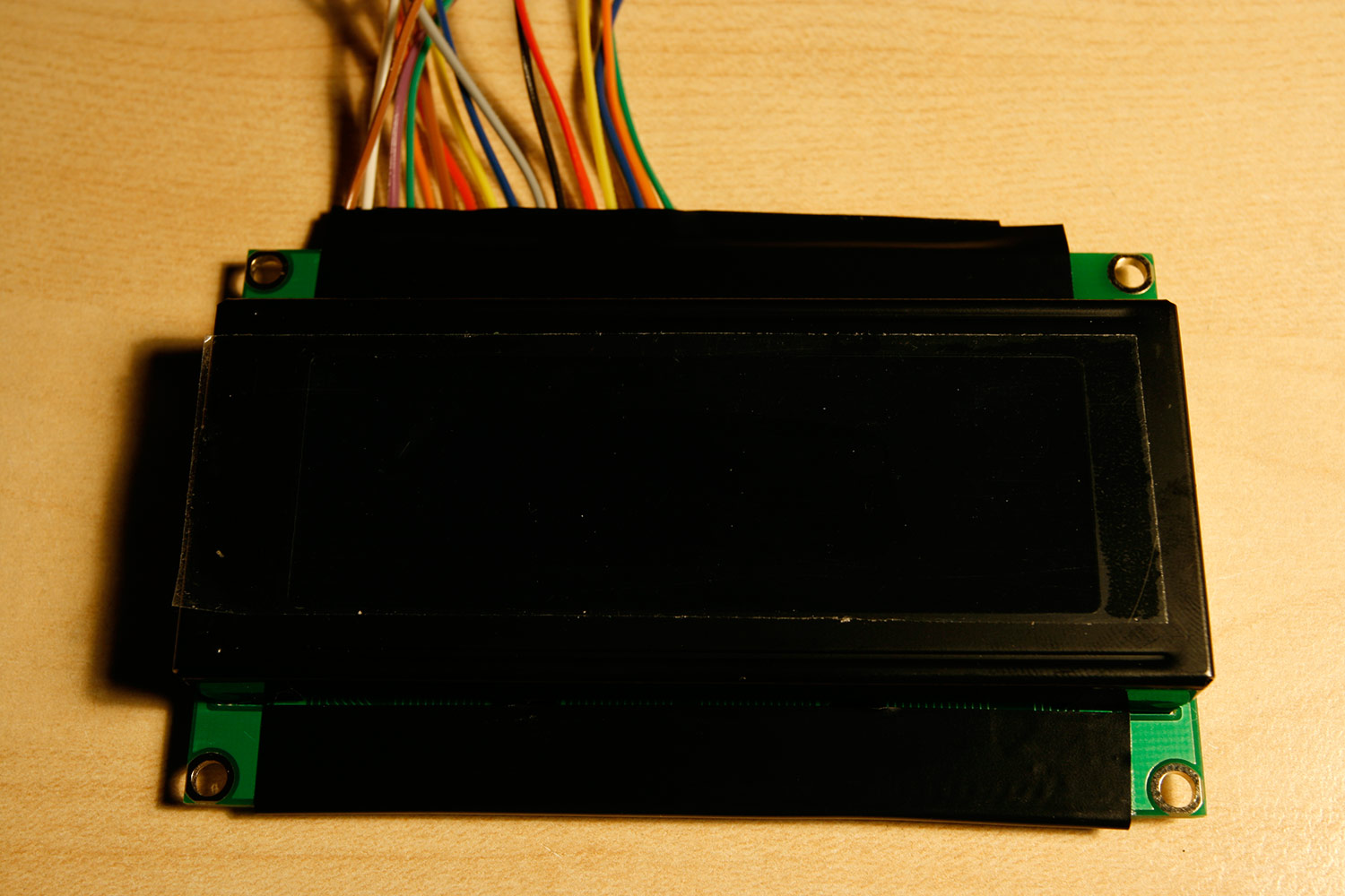
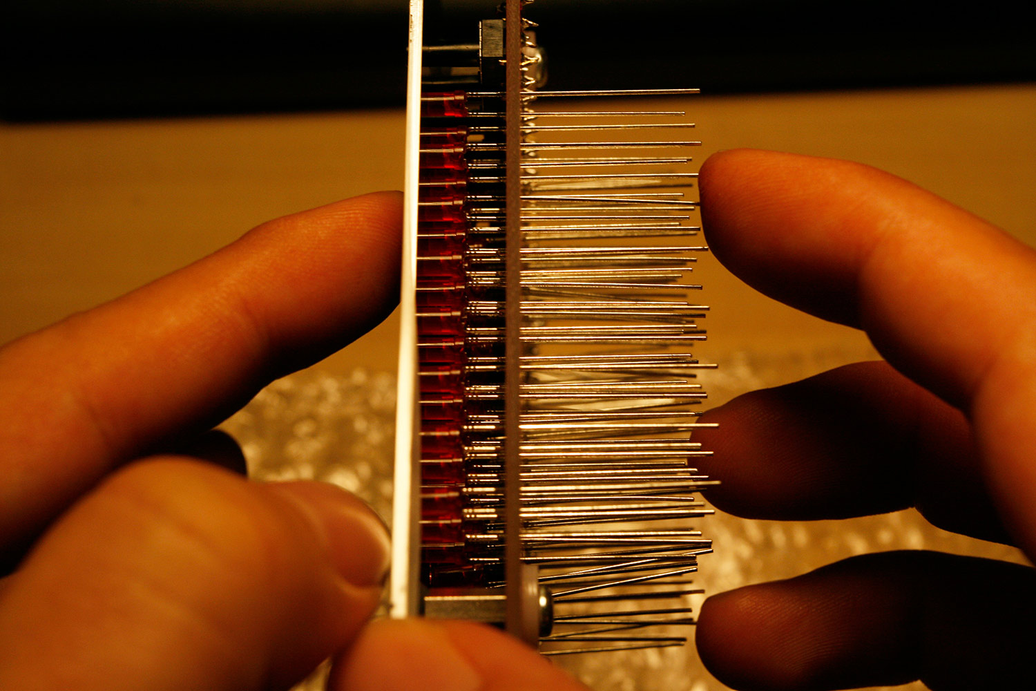
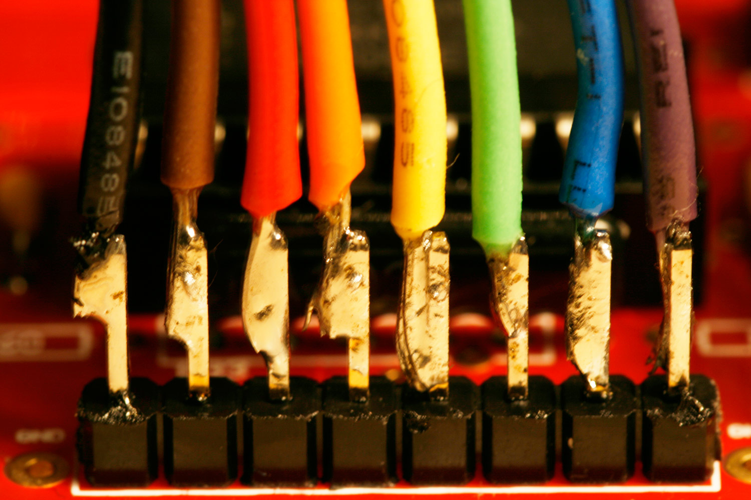
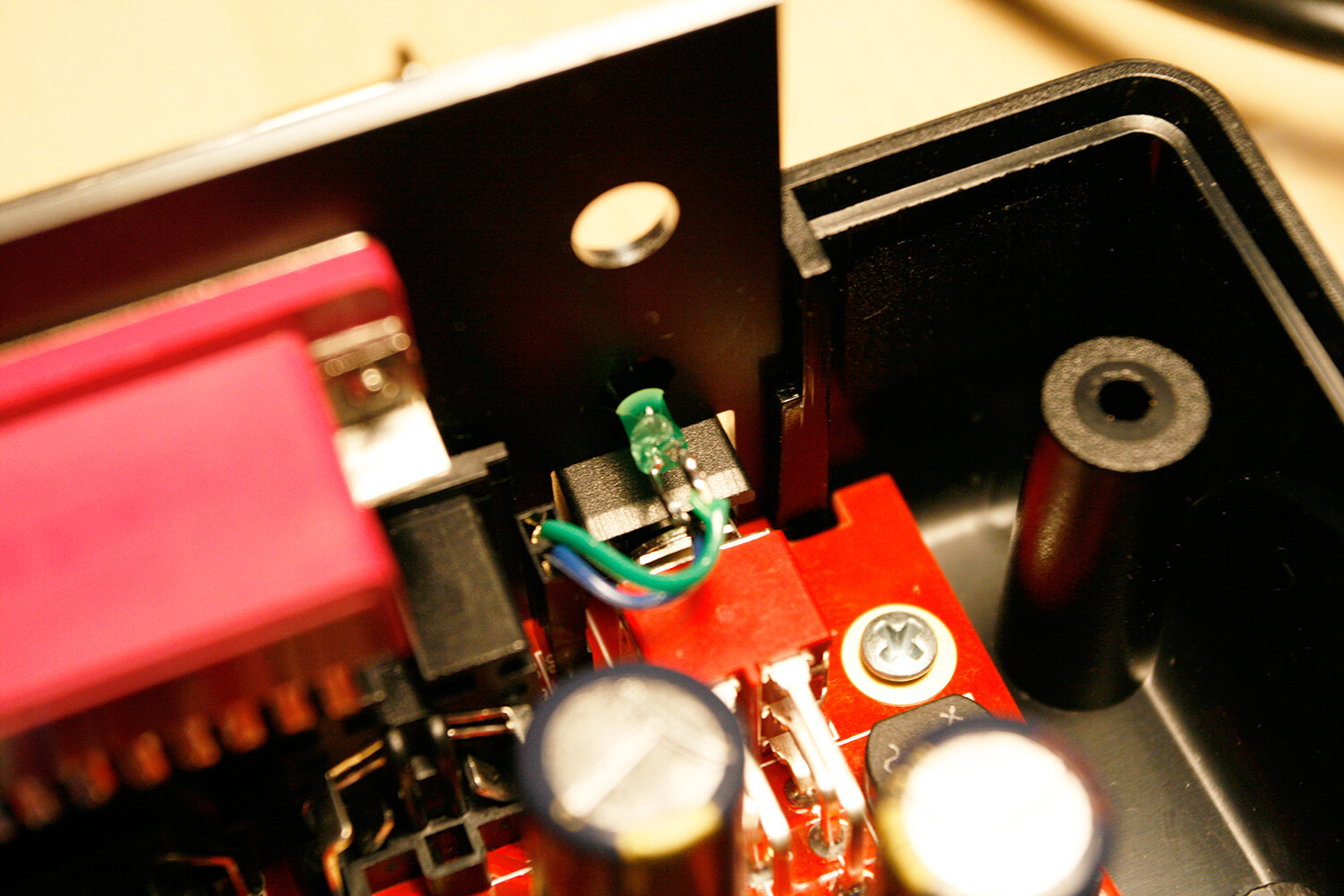
* Turn the LCD over, so that you can solder on the pads on the backside. Do not solder through the provided holes, but solder flat to the surface of the pads. Make sure, that you do not use too much solder to avoid solder bubbles on the frontside of the pads. This part of the LCD PCB will need to be as close as possible to the CS PCB, every millimeter counts. Pre-solder the pads with a bit of solder. Also, notice that the wires should arrive from the top (photo 7 shows the first connection).
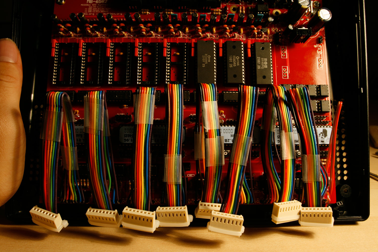
* From right to left, which is equivalent to starting from pin 1 on the base board, we will splice away leads of the ribbon cable up to the tape connection and solder the lead ends to the LCD connection pads.
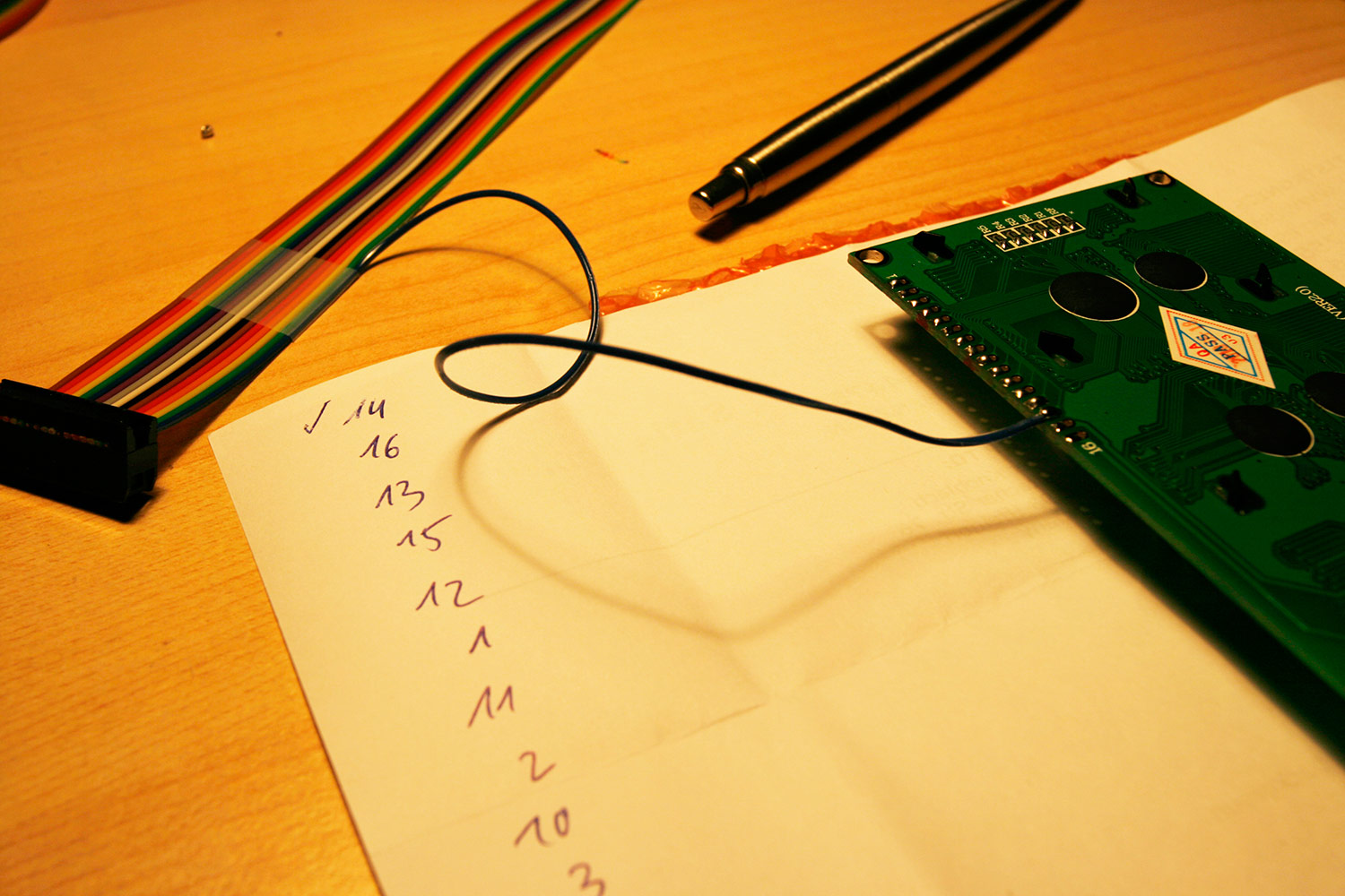
* In the right-to-left order, the leads of your ribbon cable provide you with these pins:
D7, B+/LCD+, D6, B-/LCD-, D5, Vss, D4, Vdd, D3, V0, D2, RS, D1, R/W, D0, E
* Matching this to the datasheet for my LCD, i derived the following solder order to the numbered pads on the LCD (soldering the ribbon cable from right to left):
first (right) ribbon lead \<---\> Pin 14 (LCD) second ribbon lead \<---\> Pin 16 (LCD) third ribbon lead \<---\> Pin 13 (LCD) fourth ribbon lead \<---\> Pin 15 (LCD) fifth ribbon lead \<---\> Pin 12 (LCD) sixth ribbon lead \<---\> Pin 1 (LCD) seventh ribbon lead \<---\> Pin 11 (LCD) eighth ribbon lead \<---\> Pin 2 (LCD) ninth ribbon lead \<---\> Pin 10 (LCD) tenth ribbon lead \<---\> Pin 3 (LCD) eleventh ribbon lead \<---\> Pin 9 (LCD) twelveth ribbon lead \<---\> Pin 4 (LCD) thirteenth ribbon lead \<---\> Pin 8 (LCD) fourteenth ribbon lead \<---\> Pin 5 (LCD) fifteenth ribbon lead \<---\> Pin 7 (LCD) sixteenth (left) ribbon lead \<---\> Pin 6 (LCD)
Please do the same for your LCD and do not rely on my solder order, especially regarding LCD pins 16 and 15, also read the note below.
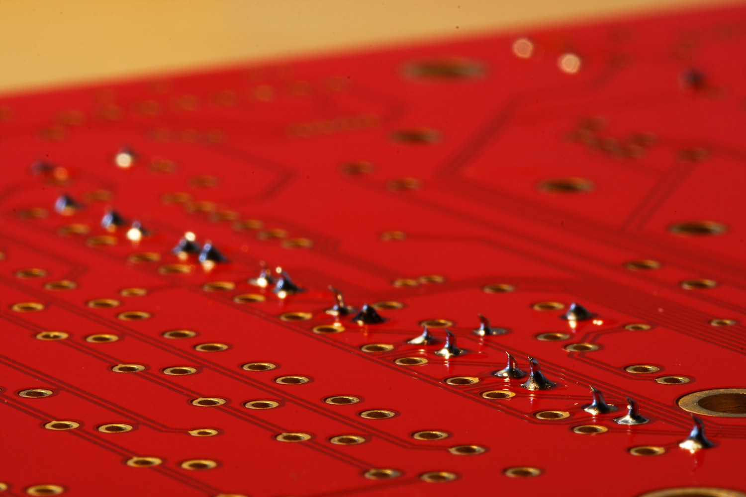
* The solder result should look like photo 8.
* Now turn over the LCD to its display side and mask the frontside LCD PCB and pad-area with electric isolation tape (photo 9). This is important, if the front side pad area is not properly masked and touches the CS PCB…
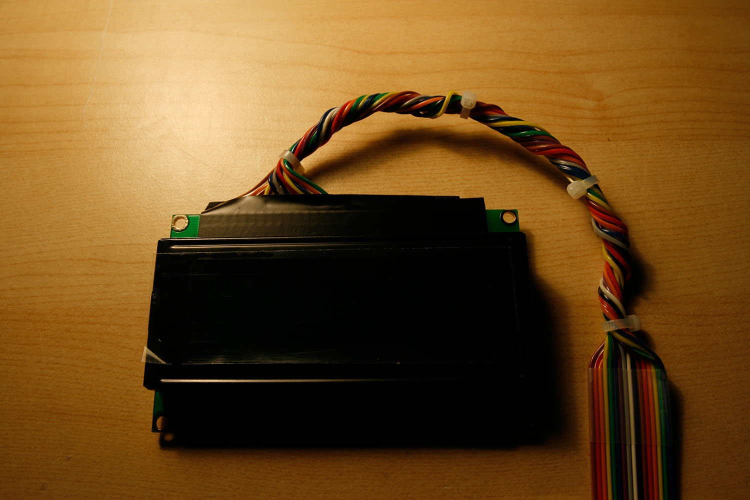
* Using small cable binders, create a round cable out of the section of spliced wires. You can also twist it a little bit to increase stability (photo 10).
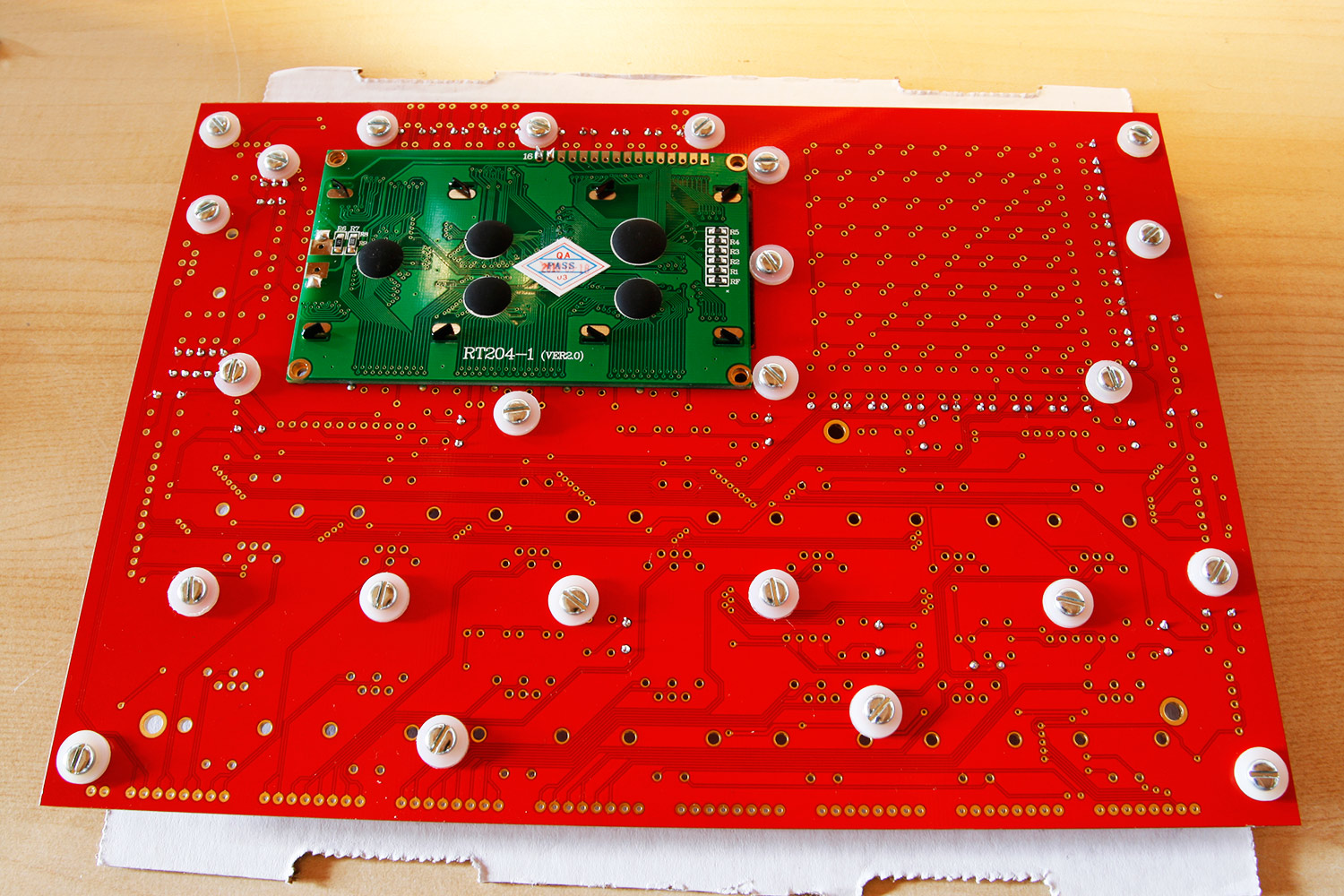
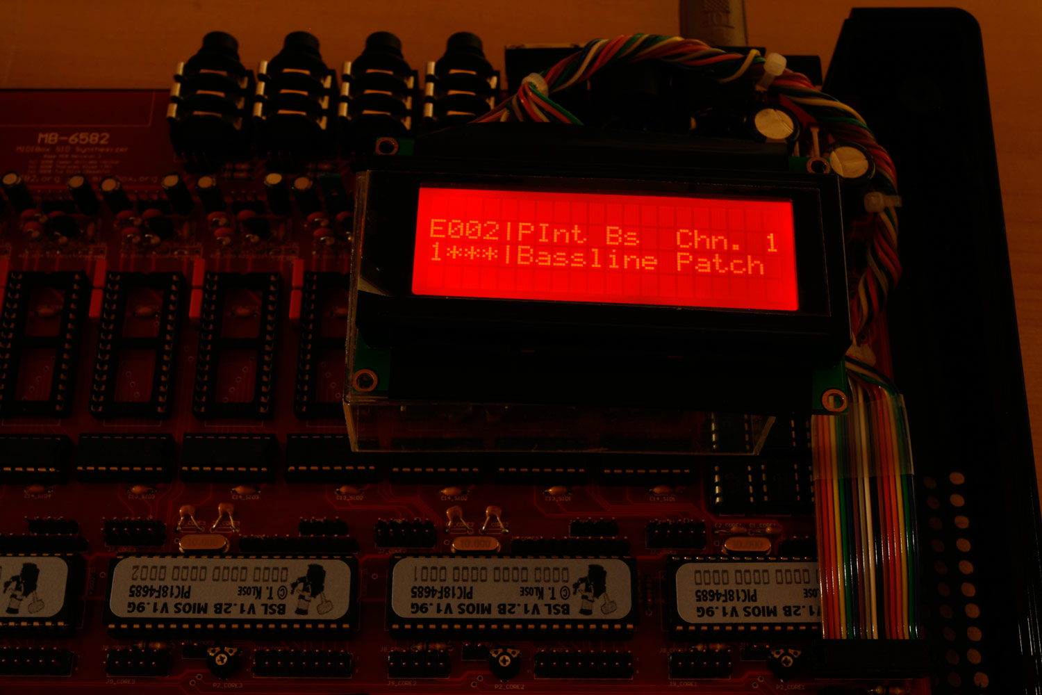
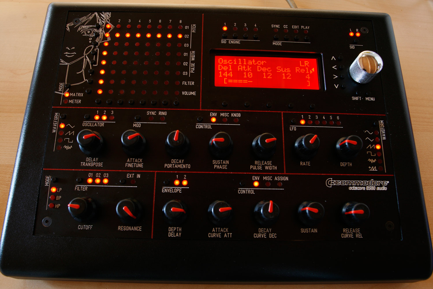
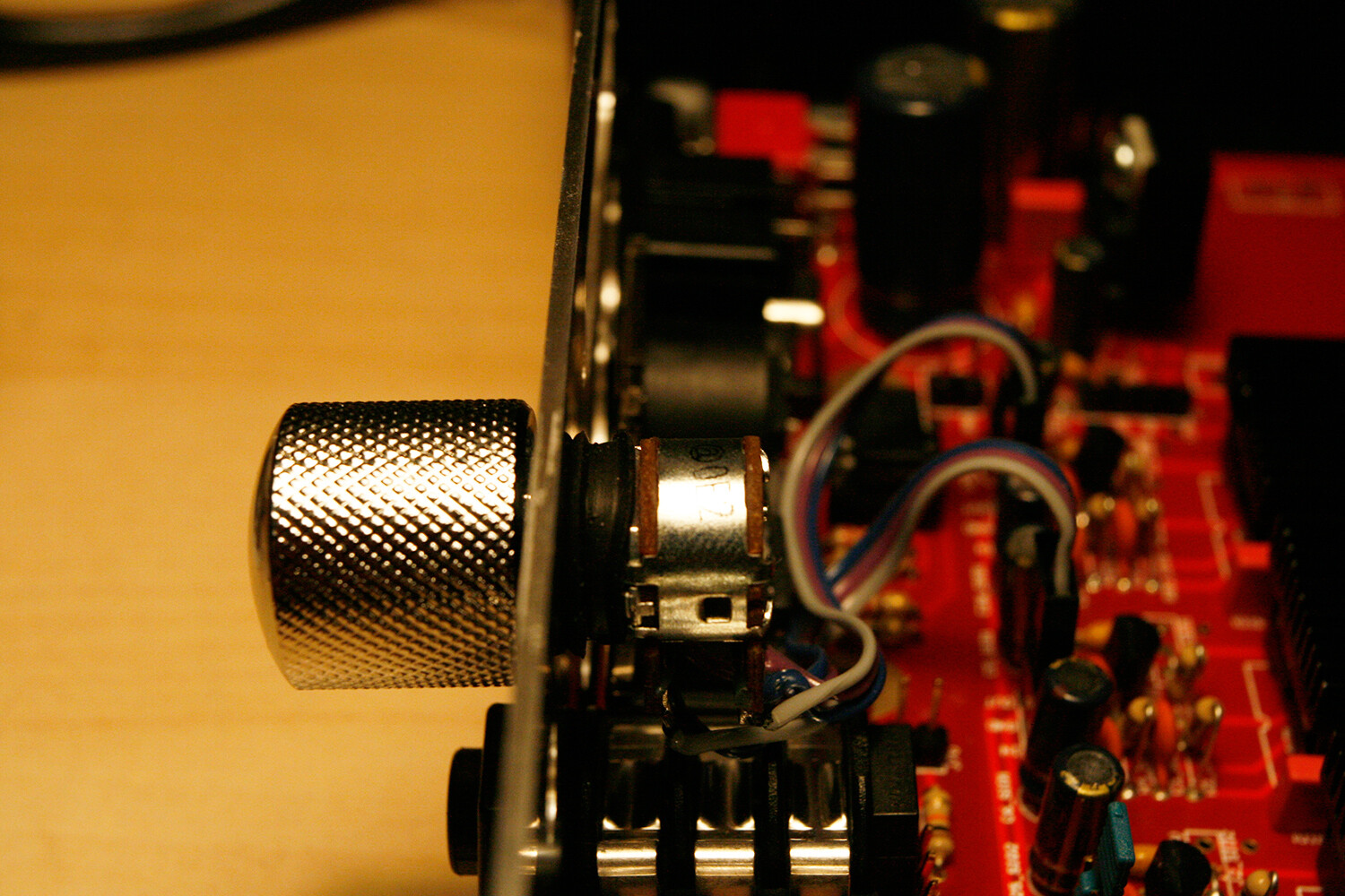
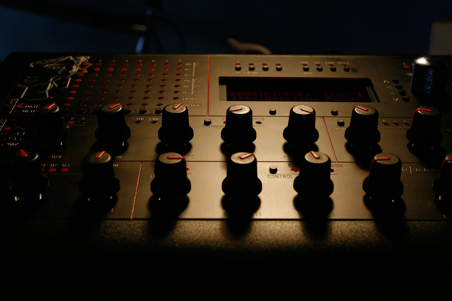
* Install and test (photo 11). You can adjust the LCDs contrast by trimming the potentiometer P2_CORE1, so if you see nothing at first, adjust here.
Note:
* The datasheet for the LCD, that I bought cheap from china was wrong regarding the backlight polarity. Not too difficult to find out, but… never trust anyone :).
* As we have not attached the connectors strain relief, make sure, when you pull the display cable out of the base board DIL header, that you grab it by the connector case, not by the cable itself.