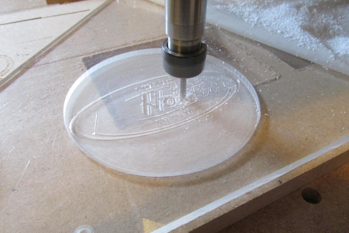
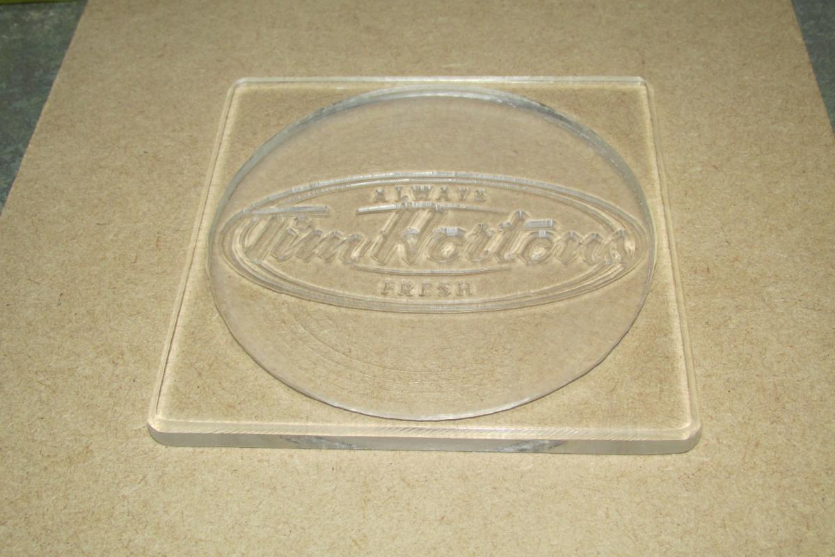
Cool! I just finished building mine, its a shapeoko. I’ll be connecting the electronics tonight. have you noticed any performance loss with the new spindle. I’ve heard that the quieter spindles have less cutting power. I’ll be fitting mine with dewalt dw600 after I adjust the runout.
Hi, actually, the new spindle is more powerful than the tool I was using, I’ve not had any problems with it’s performance, even using an underrated power supply (currently using 12V… waiting for the 48V one to arrive).
I’m more than pleased with the cutting performance, both in thickness of cuts achieved - 18mm MDF,… and speed, though the speed of cut is more limited with the type of bit being used.
I’m guessing yours is slightly larger than mine, having a full router as the spindle. Once you get started, you’ll be having loads of fun, but it’s quite a learning curve to get used to spindle speeds and feedrates… be prepared for broken bits !!
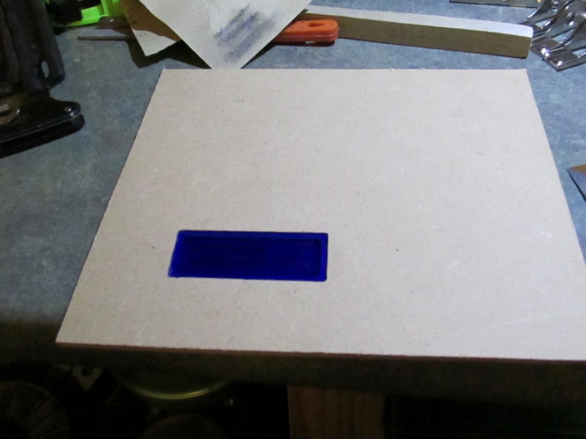
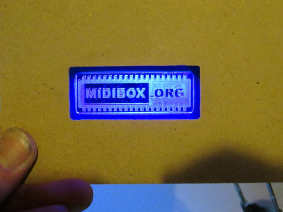
on another note, I’ve just finished a prototype for some front panel bling… very unobtrusive until power-on…
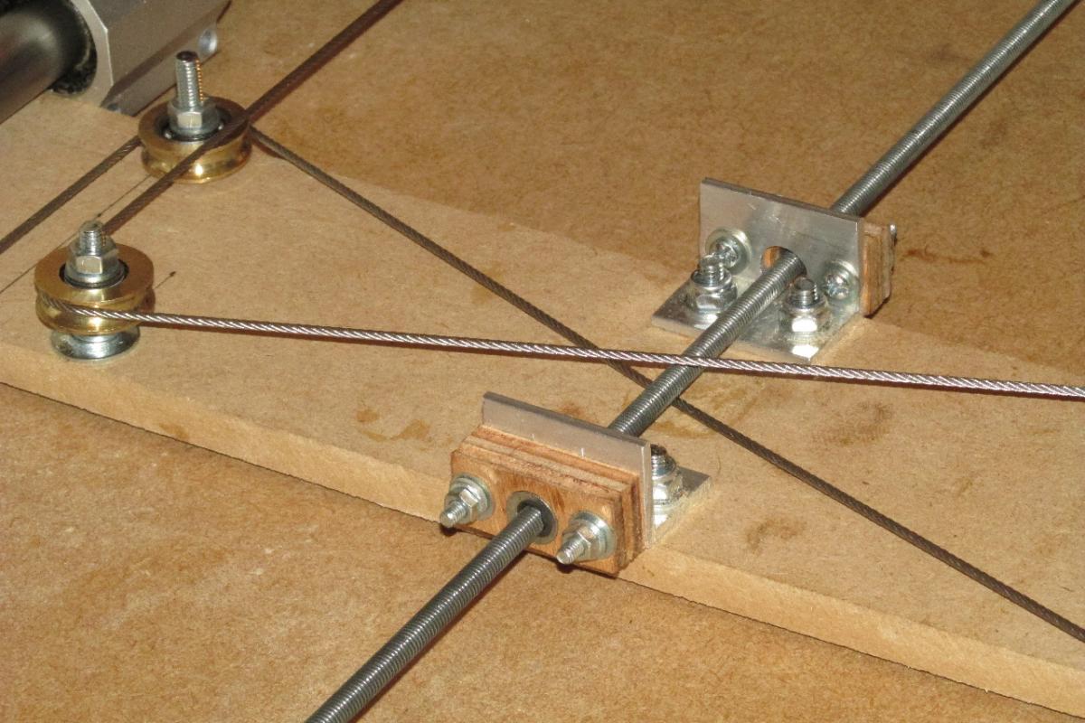
The rest of the upgrades have now finally started… beginning with the new drive mechanism for the X-axis, and the cable arrangement to stabilise the gantry and reduce the lateral play.
The 2 cables are arranged so that when under tension, each one is trying to twist the gantry in opposite directions, so that in equilibrium, it is unable to twist either way, and any slack movement is eliminated.
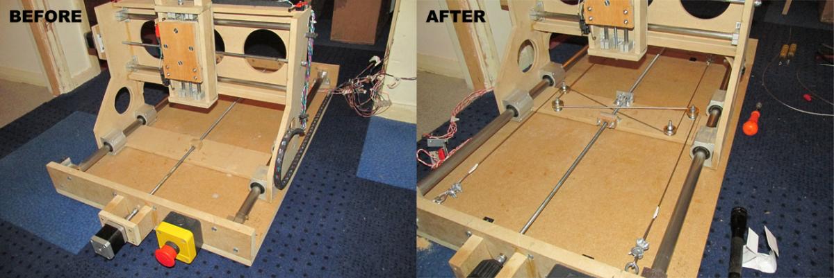
OK, slightly late addition to the upgrades… new leadscrews on the X and Y axes.
These are now in place, with much more robust bearing supports.
The gantry (my Y-axis) has a TR10x2 trapezoidal screw - 10mm dia. and 2mm pitch. The base (my X-axis) has a TR12x3.
This should see a significant improvement in speed over the original M6x1 allthread screws.
Still waiting on the new couplers before I can re-fit the motors.
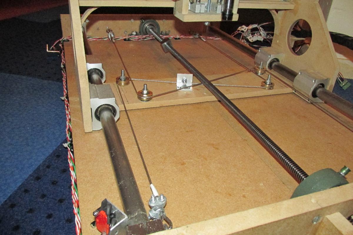
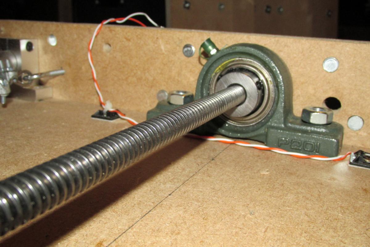
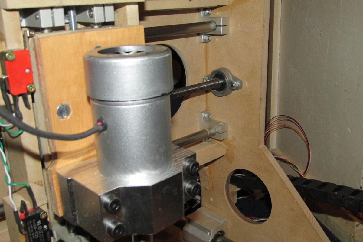
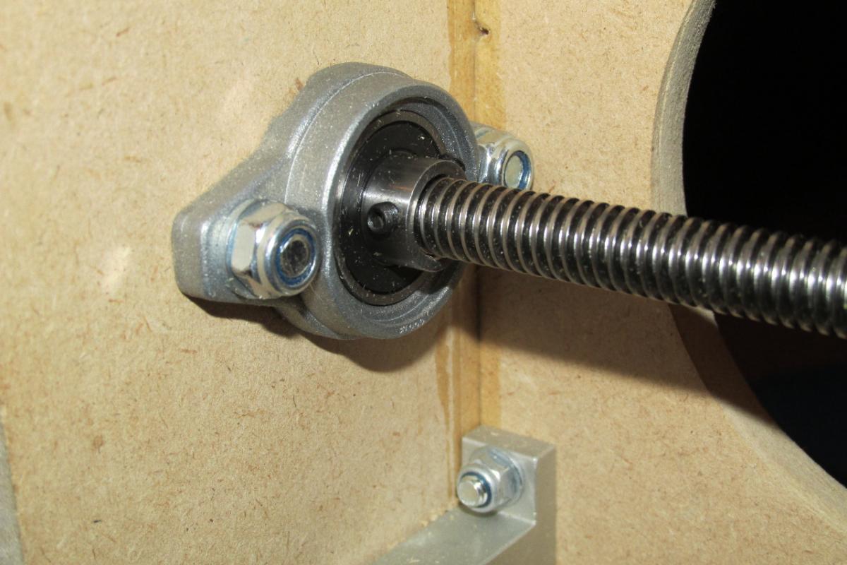
Couplers have now arrived, and the CNC is back in motion.
Initial testing shows mixed results…
X-axis (TR12x3 leadscrew) - marginal increase in speed. This was slightly disappointing, but investigation showed there is a slight wobble on the leadscrew which causes it to jam above 650mm/min.
Y-axis (TR10x2 leadscrew) - 66% increase in speed. Much better, This axis now moves at 1000mm/min. attempts to get it faster gave the same result as with the X-axis, the screw would jam.
Z-axis (original M6x1 leadscrew) - The only change on this axis was fitting the larger motor which originally drove the x-axis. Now the Z-axis moves 100% faster.
Although the speed tests were not as good as hoped for, the increase in acceleration is much more pronounced. Both the X & Y axes now accelerate 5x faster than before, and the Z-axis is 10x faster.
This results in near-instant motion at full speed, so that now it looks like a proper CNC motion.
pics and video to follow
Sorry… pics weren’t too good, and it’s stuff I’ve already posted pics of… but here’s the new video…
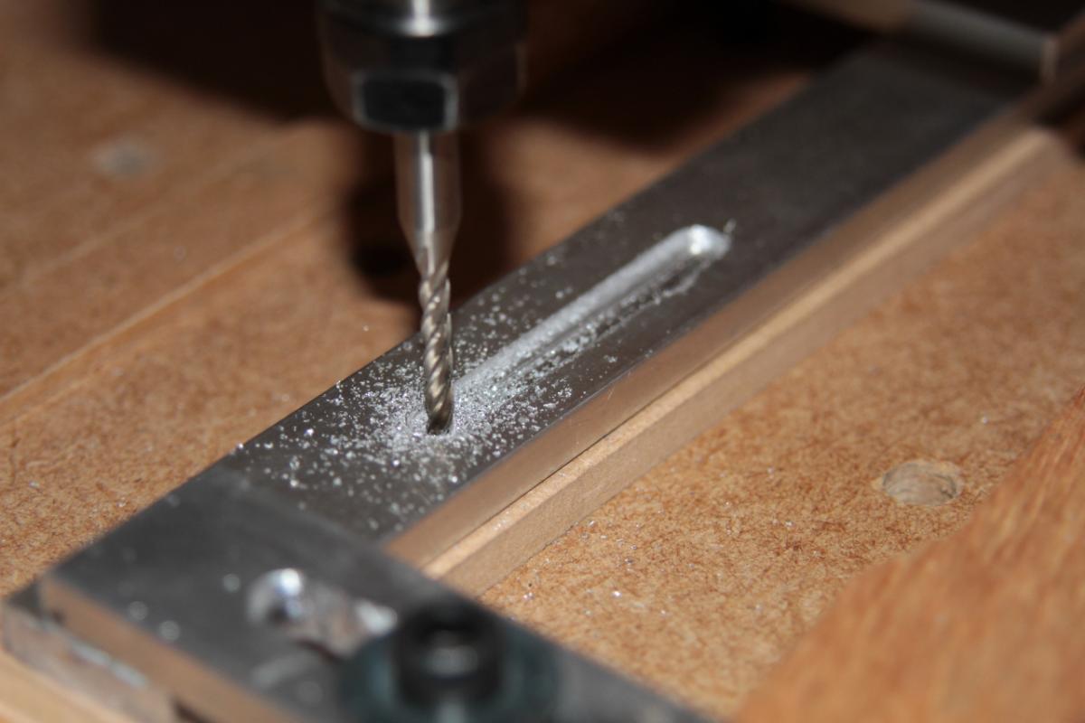
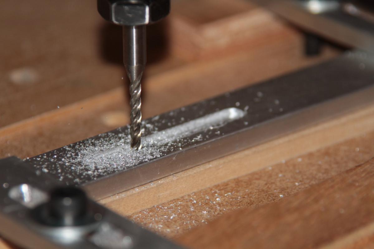
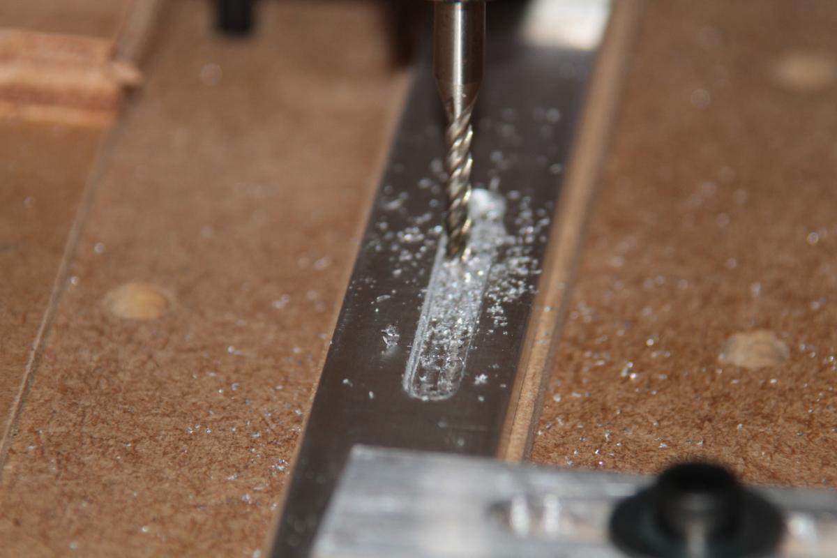
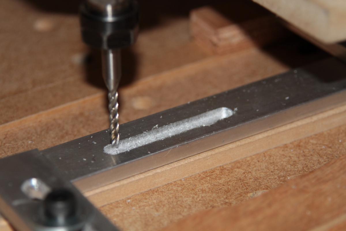
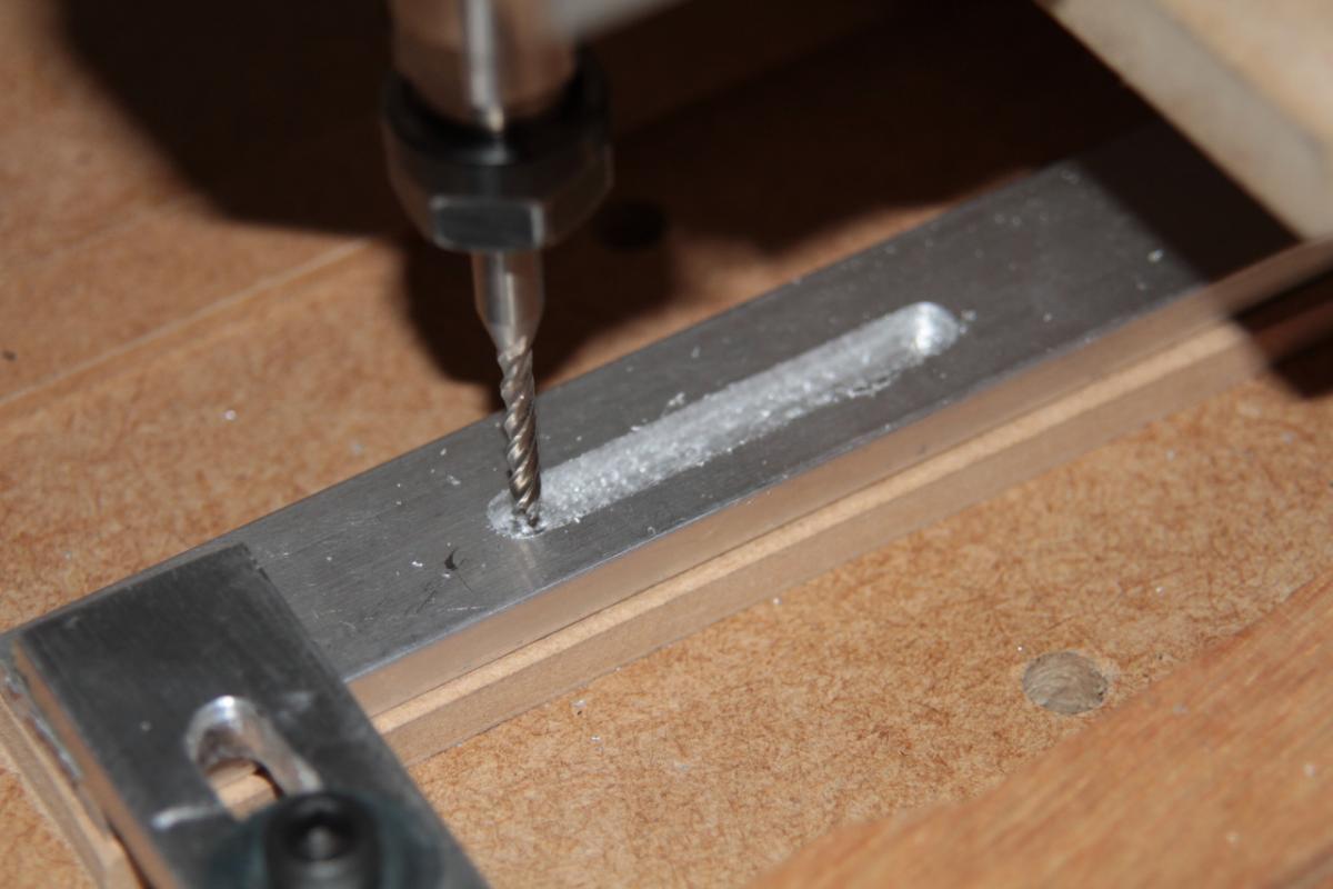
As I already know the machine performs well on wood, I decided to try the first test of the upgraded motors and leadscrews on aluminium!!
At first I had both the spindle speed and the feedrate a bit too fast, and the bit wandered off course, prompting an Estop from me, but after slowing them both down somewhat, I tried again and got a nice clean, even slot cut!! 
I’m extremely pleased… the upgrades were worth the expense and effort.
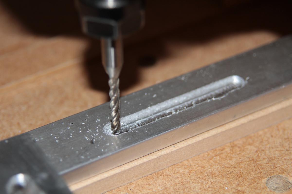
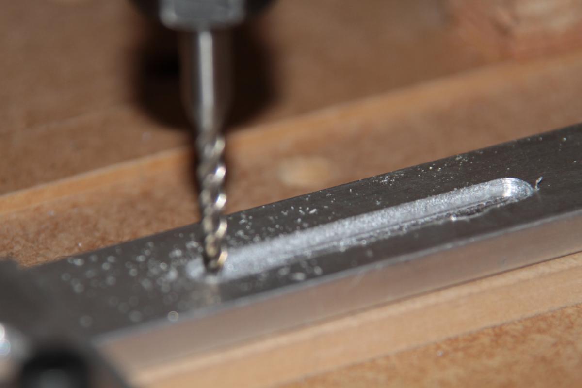
1 Like
Once again - awesome work! 
Many greets,
Peter
hello artyman ,
for this kind of work i’ll use this , 50mm/s , 0,3 max deph
Selim
Time to revisit this thread… The upgrades I made to the X & Y axes are working well. I can now get rapid moves of 1200 and 1300 mm/min respectively, which I think is quite a respectable pace. However, since I started trying some v-carving, I have been having issues with the Z-axis sticking on upward moves, so that the next downstroke would plunge the tool deep into the workpiece and ruin it. The tool mount was also showing some flexing during cutting, which was introducing inaccuracies in the final product.
Time now to re-design and rebuild the Z-axis, while sorting out a few small irritations with my first design.
- make the stroke longer so that the new spindle with my longest mill can clear the working area.
- lift the whole axis so the base is level with the bottom of the gantry to maximise working height.
- eliminate the leadscrew and nut protruding from the bottom of the axis, again maximising working height.
The new axis will now be built around a TR10x2 leadscrew (the same as the Y-axis), with a longer tool mount, and all structural parts made from 18mm MDF instead of 12mm to improve the stiffness of the tool mount.
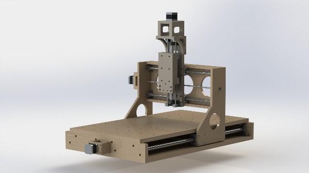
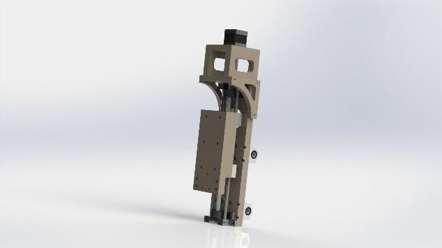
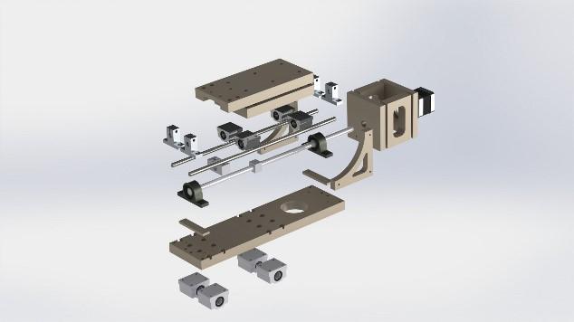
I had to slow the Z-axis right down to a crawl to stop the sticking on the upstroke, so cutting the parts for the new axis took some time, but this is now all done, and ready for assembly.
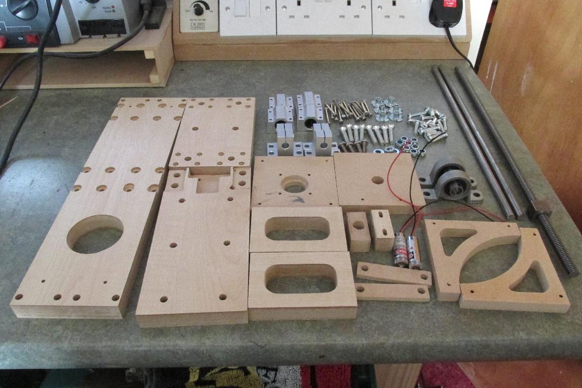
that moment when your machines procreate
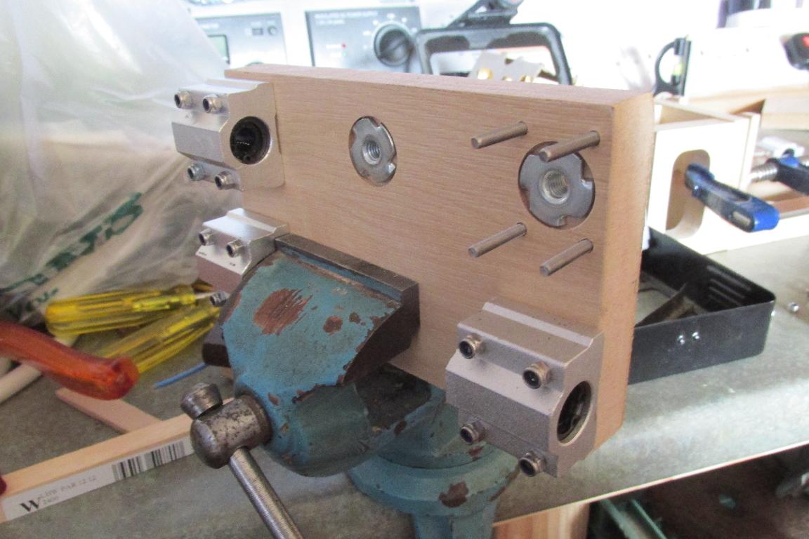
Now construction starts, First with the slider… pressing tee nuts into their recesses before I can fit the linear bearings - these are where the tool mount attaches.
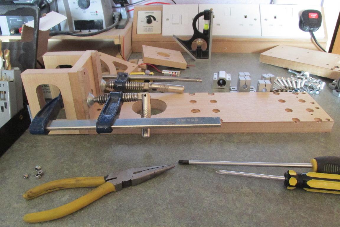
Next the main body of the motor mount is glued and screwed to the base. Thanks to the parts being CNC cut… it fits perfectly square.
Then comes a dry-fit of the rest of the hardware to make sure my calculations and cutting is accurate…
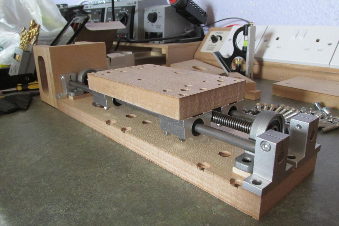
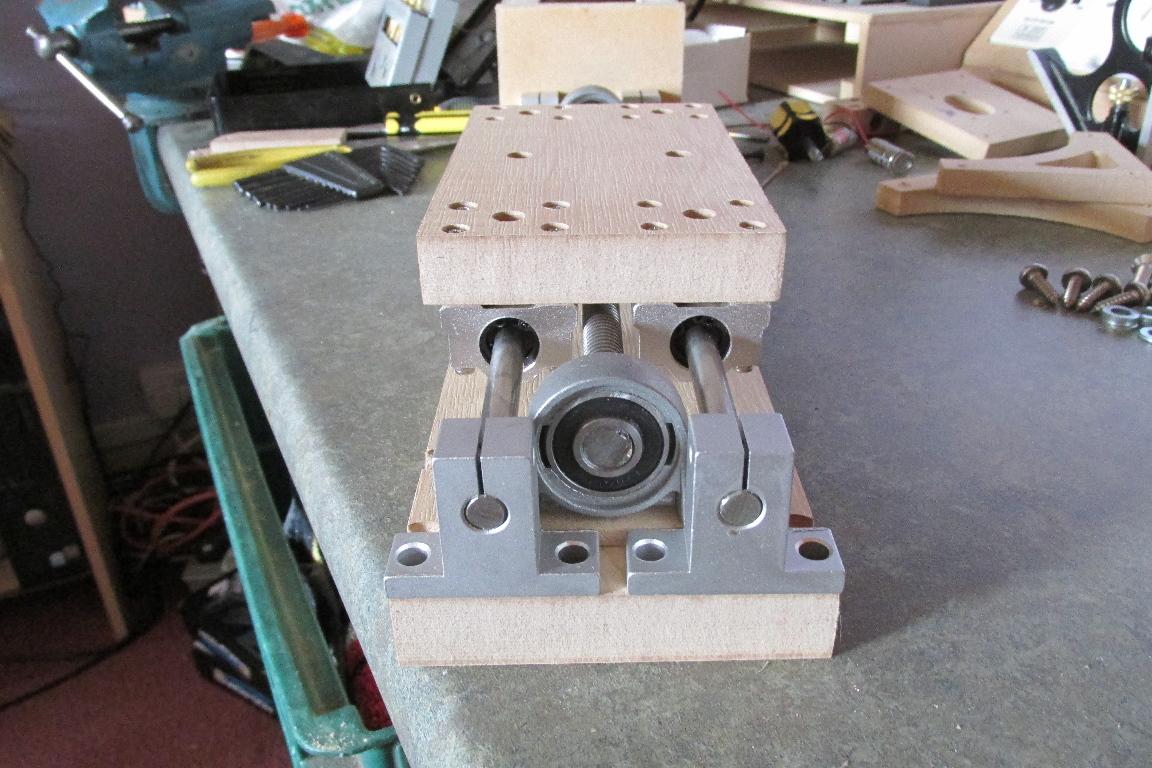
All looks good and the nut is in perfect alignment to attach to the back of the slider…
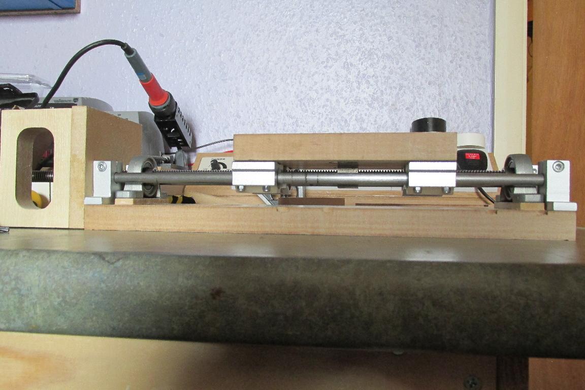
Adding the side supports for the motor mount, and test fitting the tool mount shows that all looks good to go for final assembly and fitting to the machine…
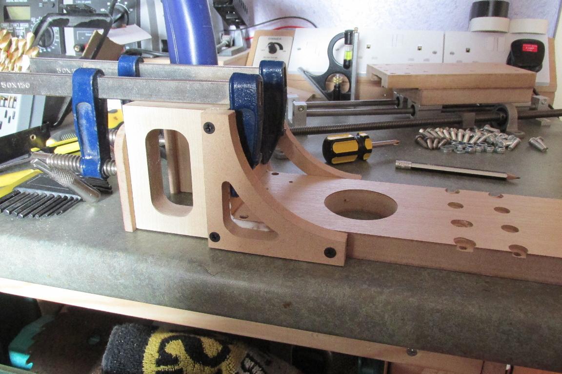
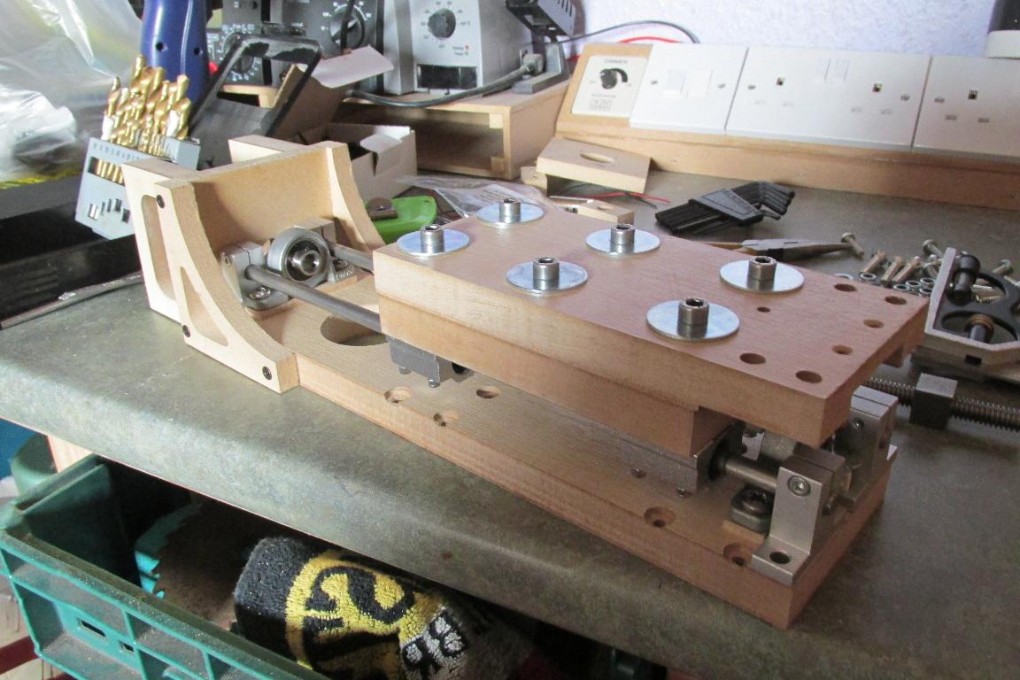
Continuing the rebuild… I’ve removed the old Z-axis, and found that my DIY anti-backlash nut had split between the threaded inserts, which was causing the sticking.
The first parts to assemble were the Y-rails onto the rear of the Z-axis, then I could fit the leadscrew bearings. (space was tight, and the lower bearing covered two of the mounting bolts on the lower set of linear bearings)
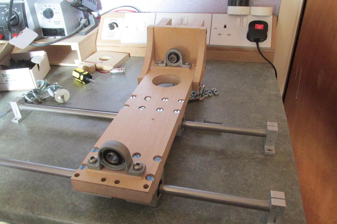
At this point I attached everything necessary to the tool mount - tee-nuts for the spindle mount, and one of the 2 laser line modules.
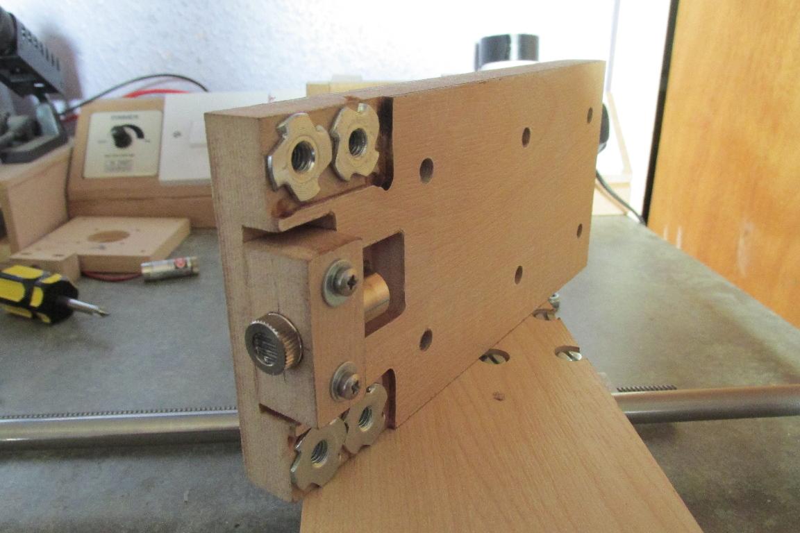
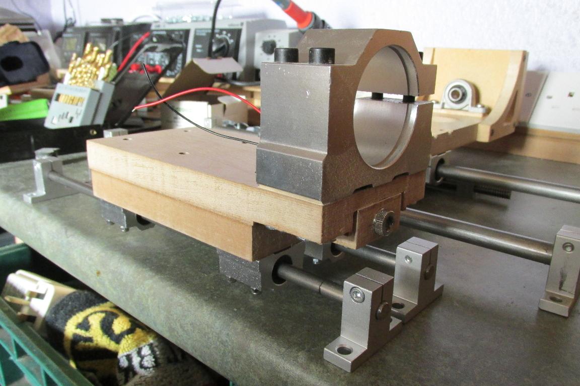
The slider assembly was then fitted to the Z-base, the leadscrew and nut fitted, and the leadscrew trimmed to size (I only had to cut about 25mm off the length I bought )
The whole Z-axis/Y rails assembly is now fitted to the CNC, and a new home switch mounting constructed.
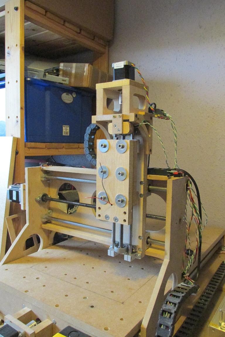
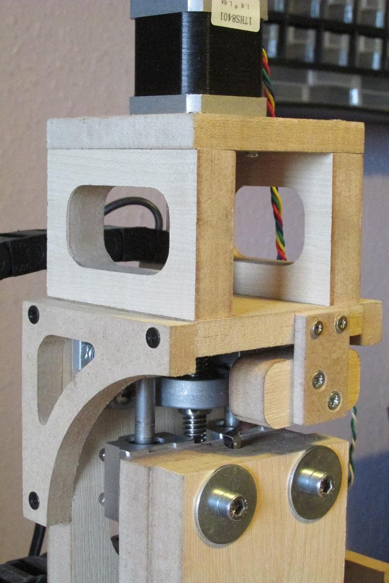
The last pic shows that I’ve achieved the design goals for the extra clearance.
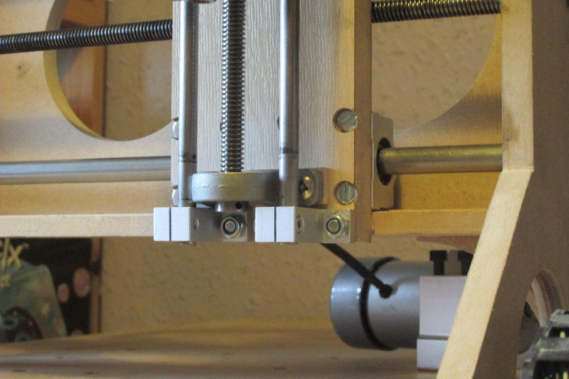
Initial testing has shown a rapid rate of 1800mm/min and a stroke length of 105mm (previously 60mm)… a significant improvement over the previous incarnation !!! :happy: :hyper:
It’s crunch time !!! Time to see how it cuts
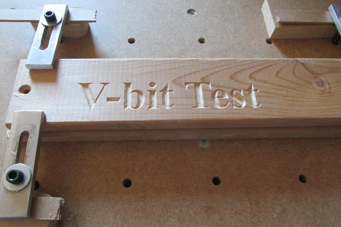
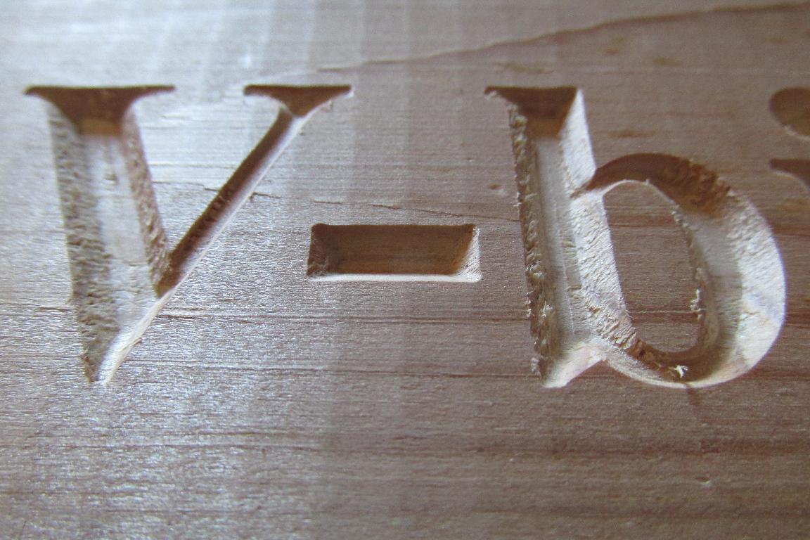
With a V-carving bit in the spindle, and a test program loaded… see the results for yourself…
..and here’s some stills of the results..
The final part of these planned upgrades is now fitted… LASERS !!!
The Y-alignment laser was fitted when I made the tool mount and is an integral part of it, now I need to mount the X-alignment one…
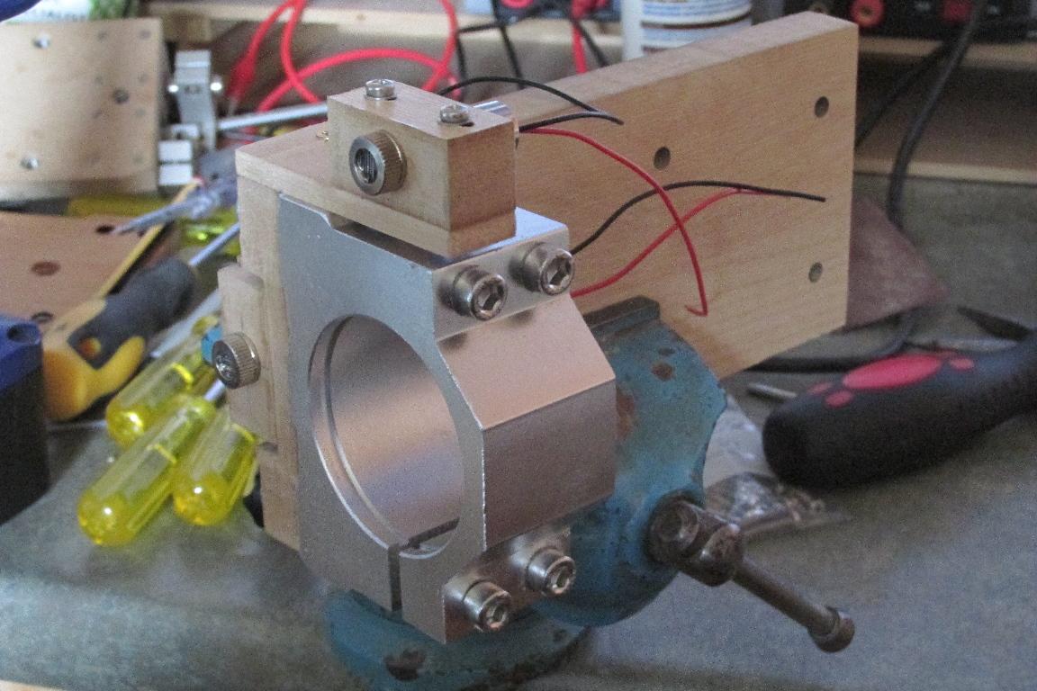
Yes… I know the mount doesn’t look like it’s in line with the spindle mount… and it isn’t - but the laser IS square to it.
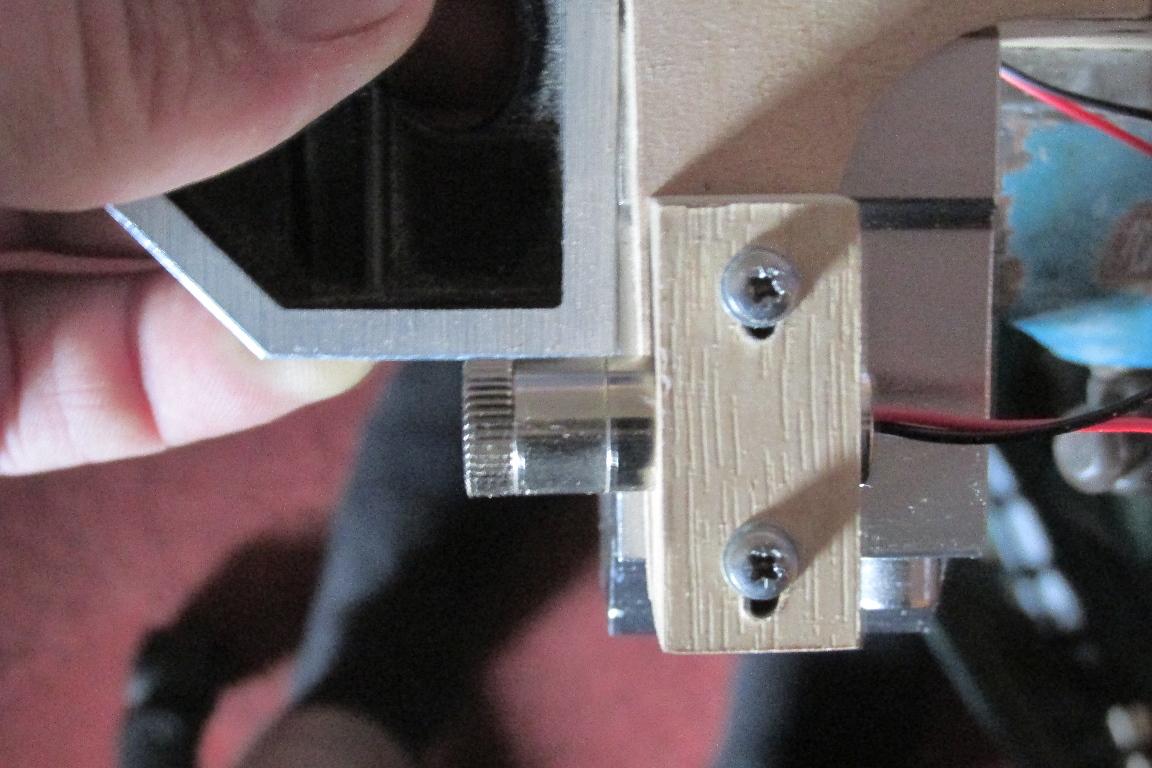
With the lasers mounted and wired up… time to test they work with my wiring…
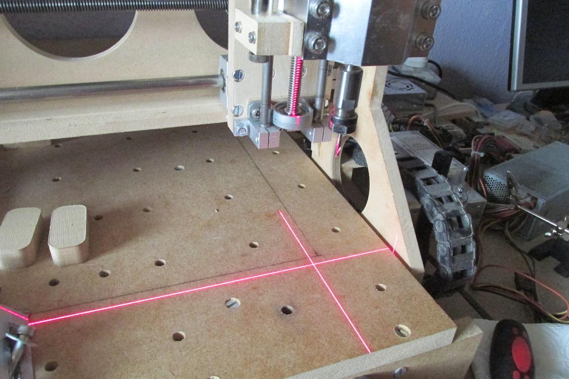
… and they do.
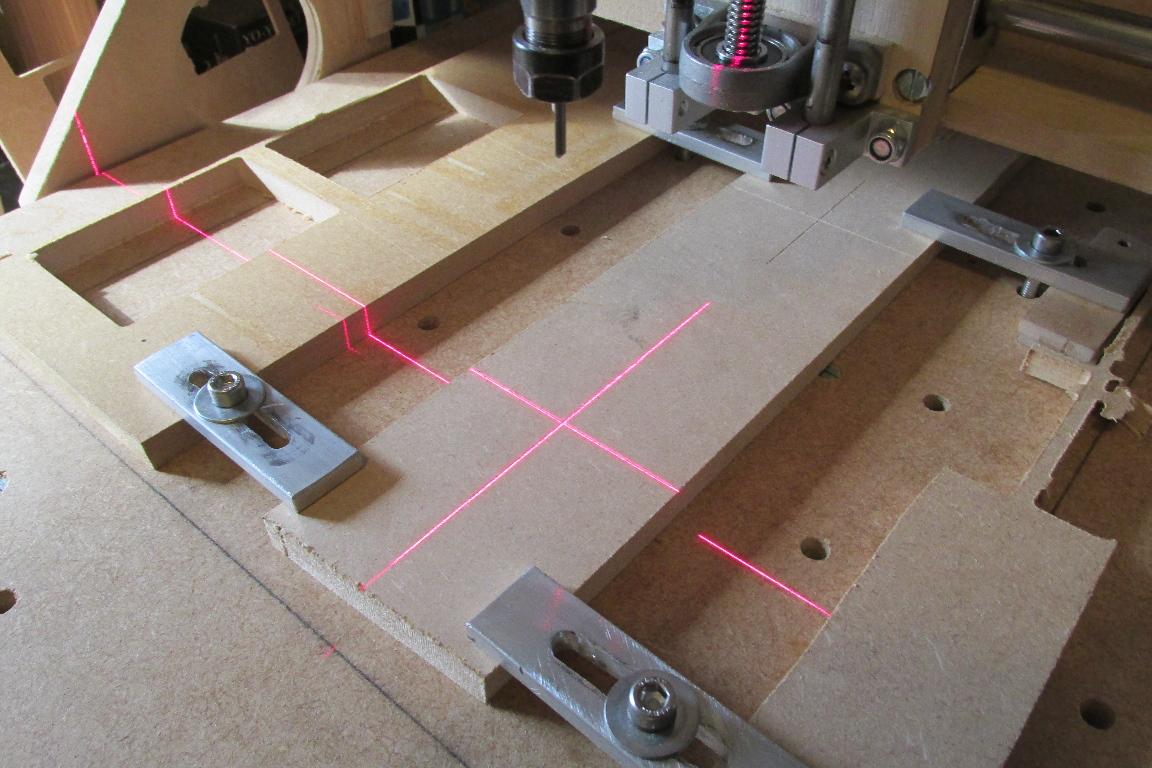
The final step is focusing and alignment. I decided to have them focused when the Z-axis is in the home position, as they are not needed while cutting, so being out of focus in any other position is not a problem.
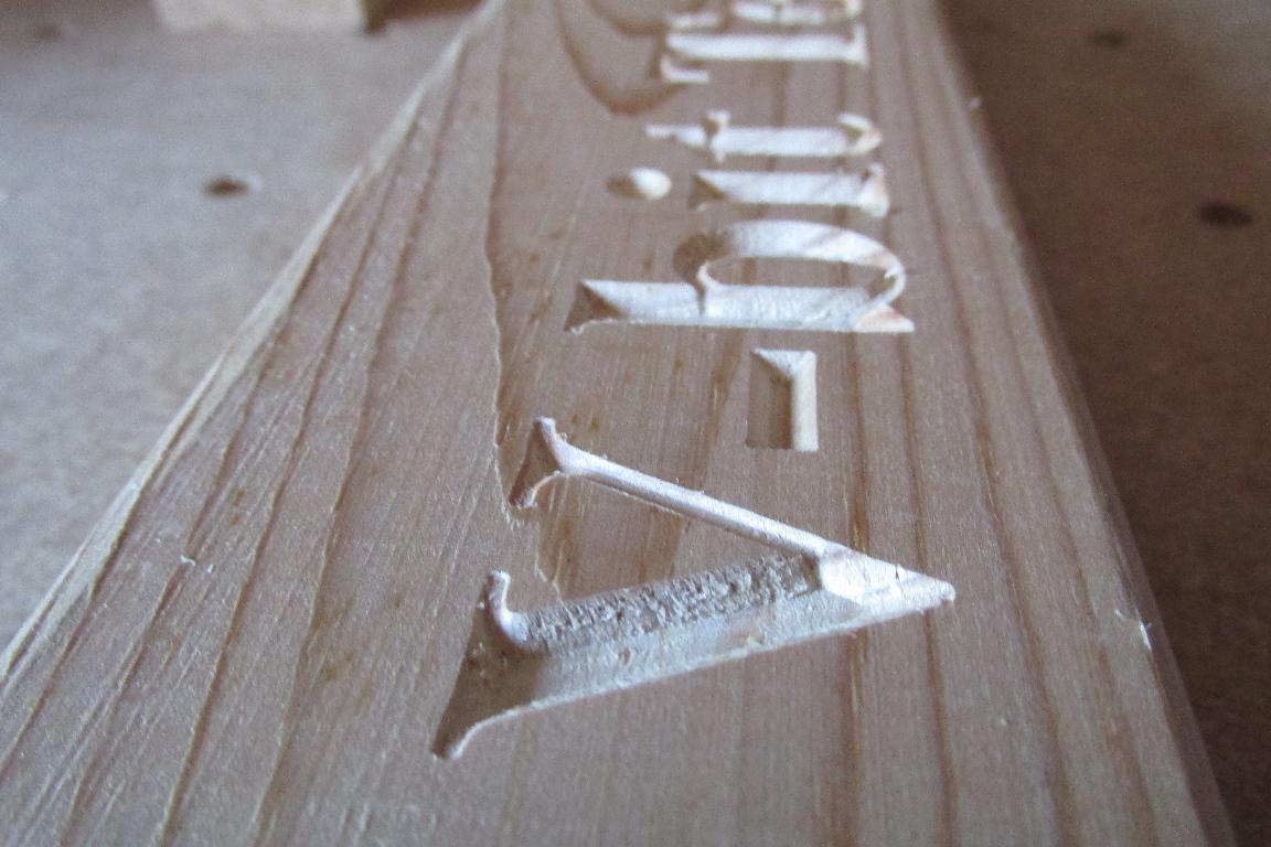
Firstly, create some G-code to engrave a crosshair that I know is in line with the X & Y axes, and the origin at the centre. I did this with a 0.3mm 90deg engraving bit at a depth of 0.2mm.
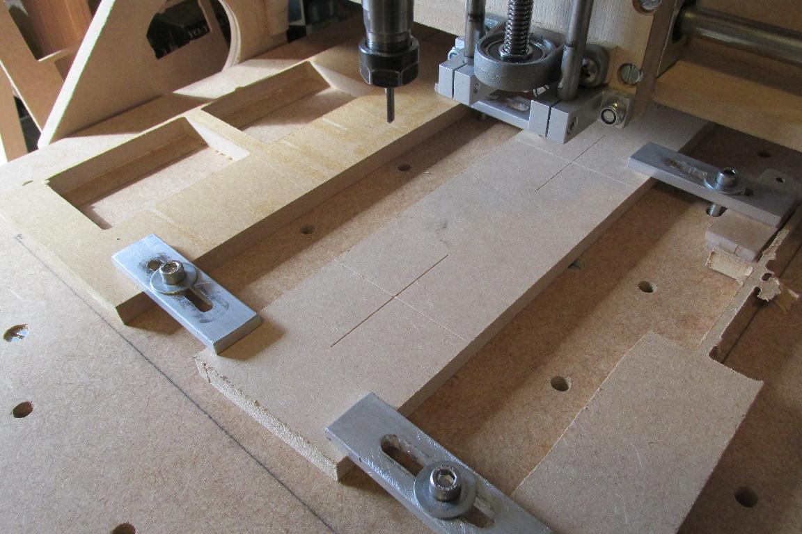
Now with the tool at x=0, y=0, and z=home, I can switch the lasers on and line them up with the engraved lines.
This way I can use the laser lines to aid in positioning my workpiece as well as having a visual reference of the tool position.
After much experimentation and tweaking of the CNC I believe it’s finally working properly… so I decided to make myself something small that uses multiple tools…
Starting with a 6mm end mill to pocket the recess… then a 3mm, 90deg 0.3mm engraving bit to carve the design and put the chamfer on the outer edge… finally a 3mm end mill for the cutout…
YES… it’s a COASTER !!!