Video of the first test, after lots of head scratching during the configuration of it all…
Video of the first test, after lots of head scratching during the configuration of it all…
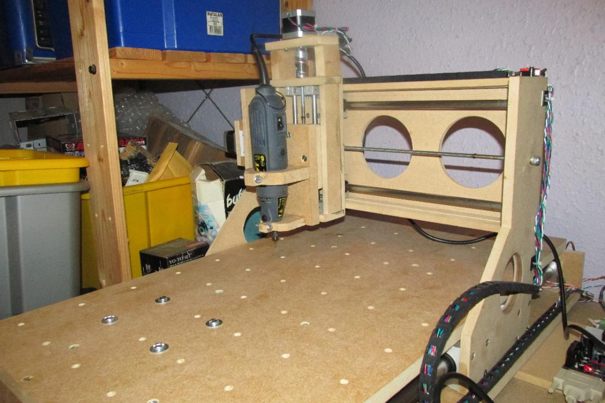
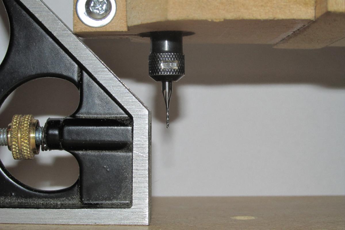
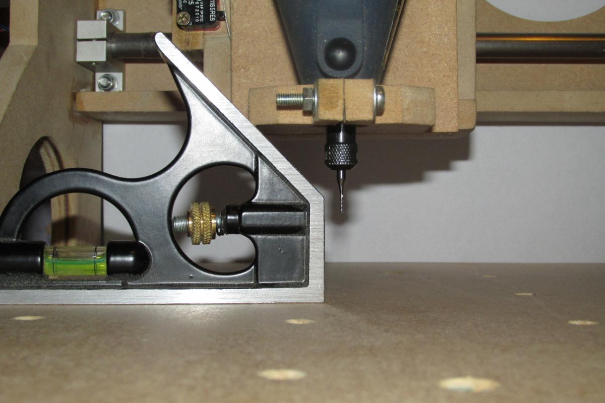
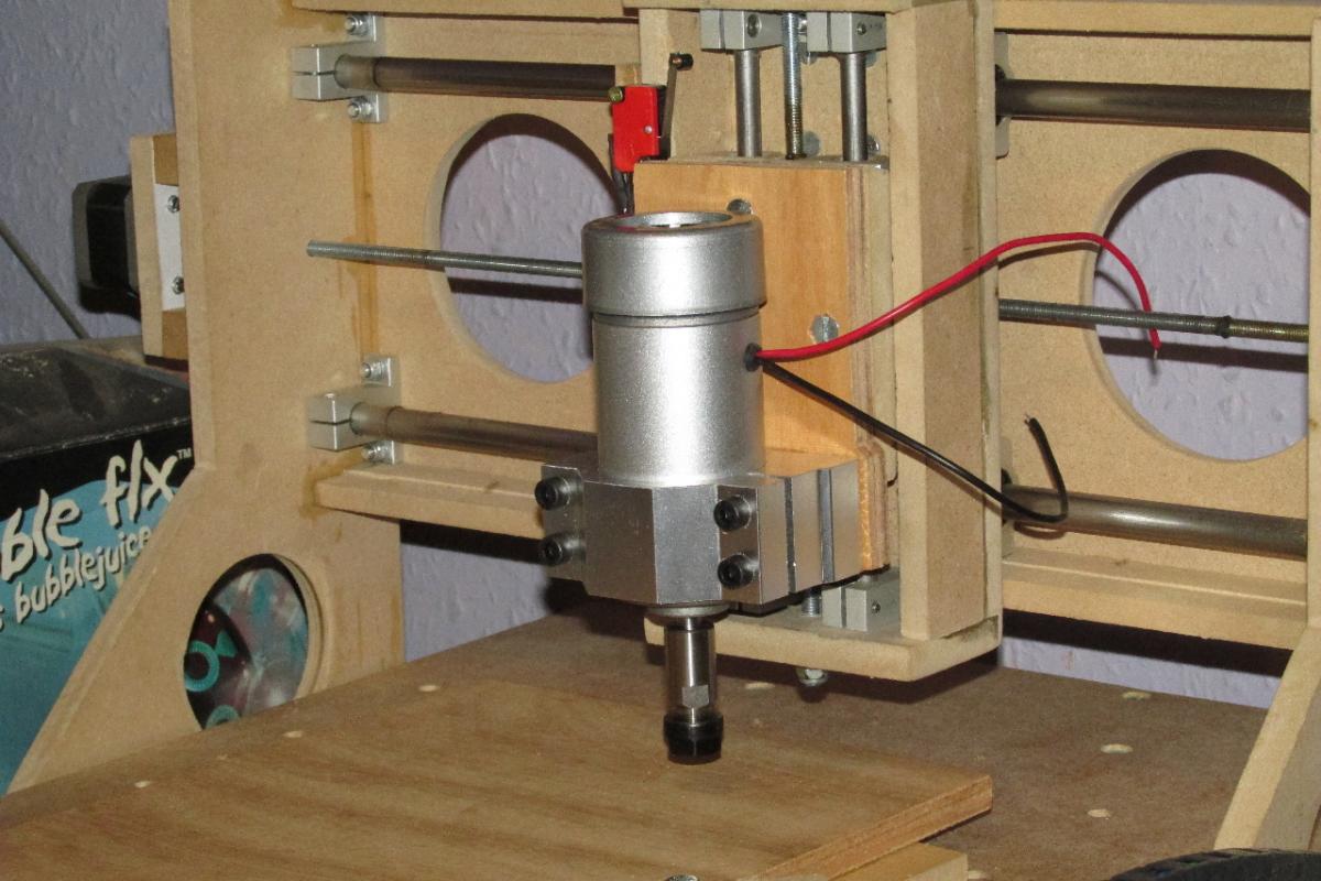
Finally, after my busiest time of the year at work… I’ve managed to find time to fabricate the tool mount and fit my spindle.
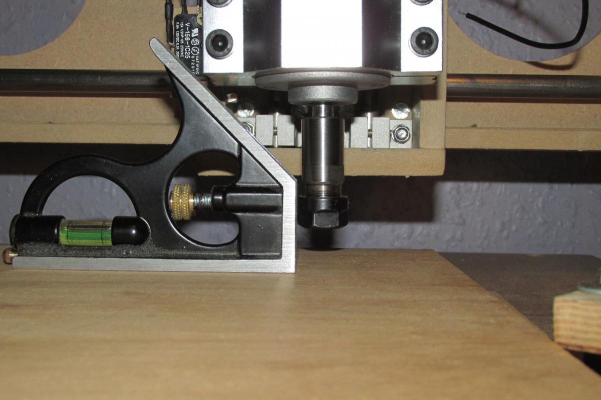
I’m incredibly pleased… not only is the tool solid in the mount, but it’s also perfectly perpendicular to the table !! 
 :happy: :hyper:
Next step is to buy the full version of Mach3, then I can start cutting!!!
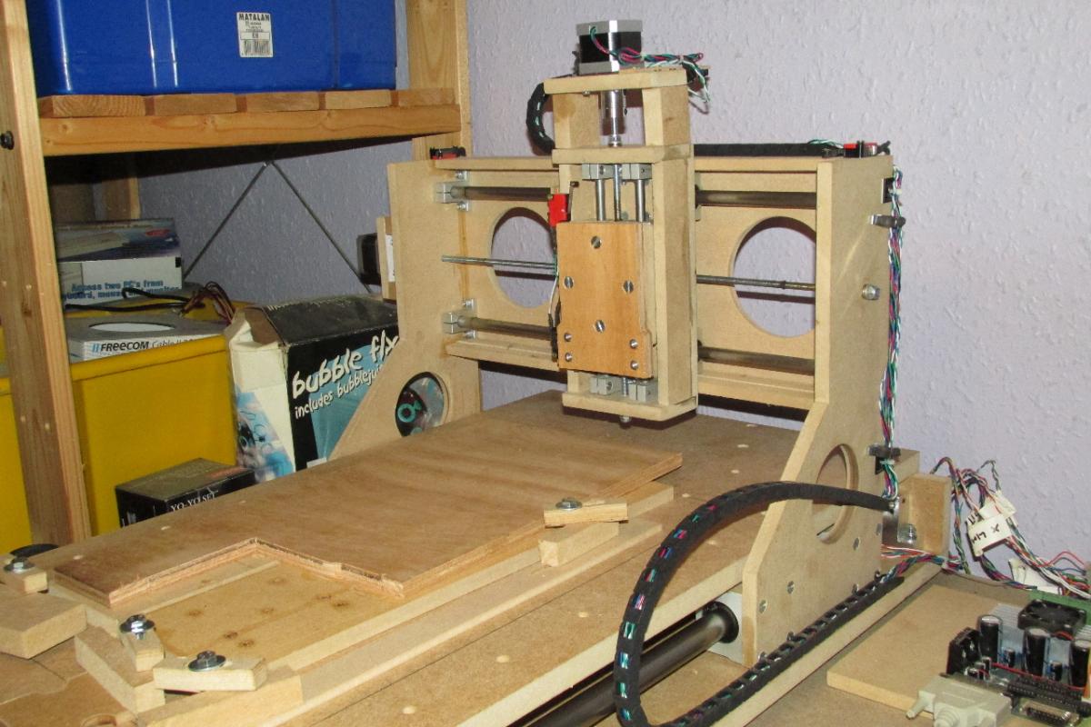
Cutting has started !!! I now have a working, completely self-designed and built CNC router ! :hyper:
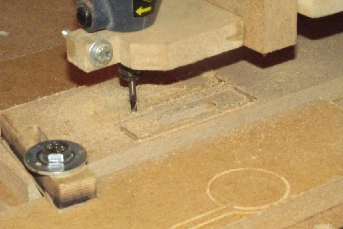
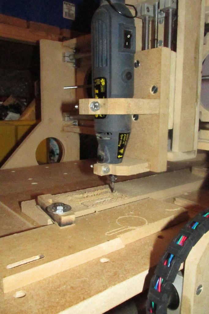
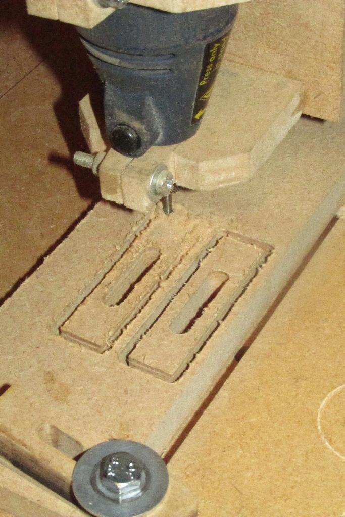
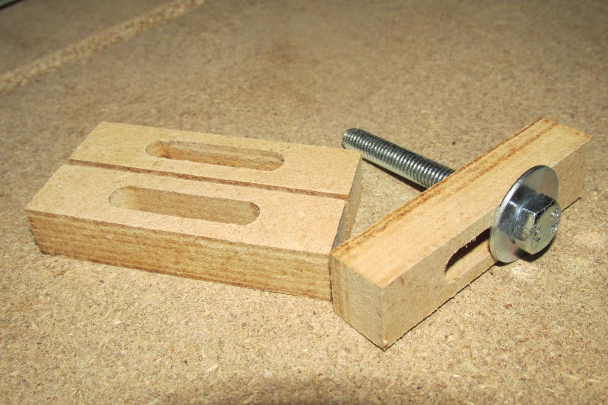
First job for the CNC… make some clamps…
Simple job to start with, but they came out really well…
every pass around the profiles was perfectly aligned…not bad for a machine made from mostly reclaimed scrap MDF !!! 
I like it very much! Good quality cuts! And with the thickness of the wood you managed to cut, I am quite sure, it would work on aluminum or thin carbon fibre plates, too!
The best thing is now, that you can reinforce parts of your CNC with its own self-made parts, if you think it is necessary… a self-improving machine - skynet is online :-).
Would you give us a short list of parts, ie. stepper motors/control logic kit used in your CNC?
Many greetings!
Peter
Thank you
The next plan for it is another tool - 200-300mW laser for ‘engraving’
OK… for Hawkeye, and anyone else that is interested… a brief synopsis of the parts used :-
Z-axis - 8mm stainless steel rails + linear bearings, NEMA17 48 Oz-in stepper
Y-axis (Gantry) - 12mm rails + linear bearings, NEMA17 48 Oz-in stepper
X-axis (Base) - 20mm rails + linear bearings, NEMA17 78 Oz-in stepper
all lead screws are standard M6, 1mm pitch threaded bar, with thrust bearings on each end.
The fabric of the machine is reclaimed 12mm MDF for the Y & Z axes, new 18mm MDF for the base.
Control electronics are a generic 3 axis TB6560 stepper driver board - combined breakout board and 3x stepper drivers
All of this is controlled through Mach3 software.
Wow, this is awesome! Very good job!
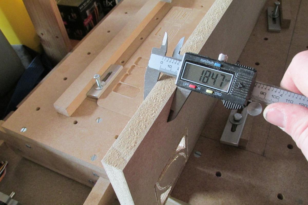
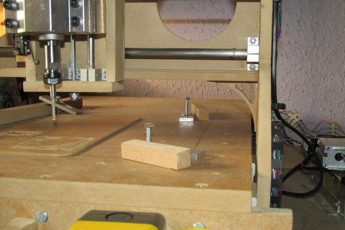
Found one problem with the build… machining a long cut from front to back, the cut gradually got shallower until the tool came out of the workpiece.. NOT GOOD!!!
after some investigation, I found that the endpiece at the back was about 1mm shorter than the front, so the table had a slight slant on it.
THE SOLUTION:- machine some shims to place betwen the table and the endpiece.
Now the back is slightly proud by 0.2mm (I can live with that), which should settle down as the MDF shims compress under the bolts.
As far as cutting goes, I started out very conservatively at 2mm/sec and a fast spindle speed. but found that while cutting well, it was also prone to burning the wood. So… I decided to slow the tool down a bit to half speed (about 12000RPM) and gradually ramp up the feedrate, now I can cut at a whopping 6mm/sec, almost as fast as it’s rapid rate (which is the fastest it goes).
@Johey - Thank you, It was a long build, but SO satisfying to see it working.
I can imagine!
Can you drill and engrave aluminium panels with this?
Can you drill and engrave aluminium panels with this?
…and/or acrylic LCD windows - though I’m owning a CNC myself I never was able to get good results while cutting acrylics though this was probably a result of using no fancy (i.e. expensive) cutting bits. I used Cut2D program to create the tool path for Mach3, in case you’re interested in giving it a try…
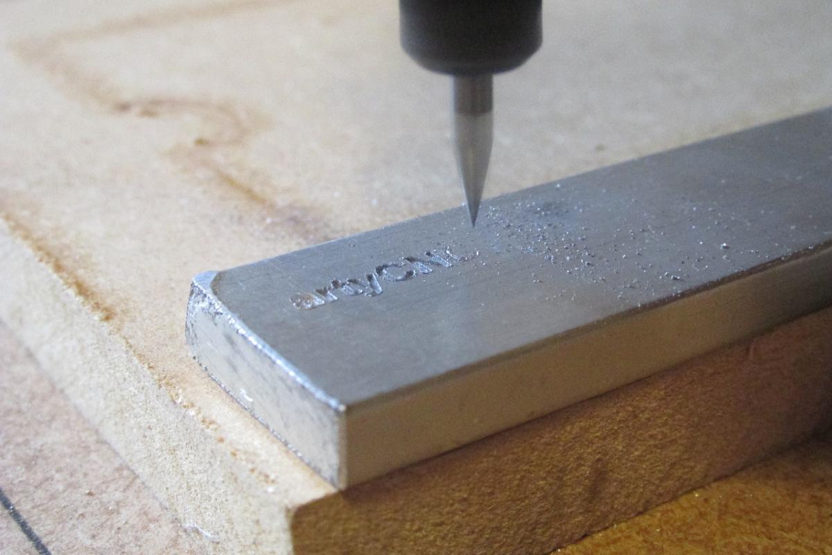
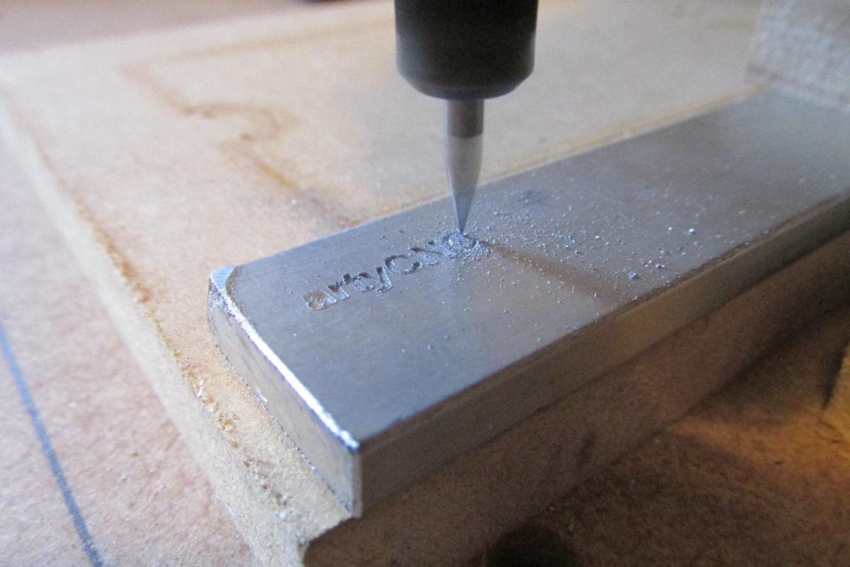
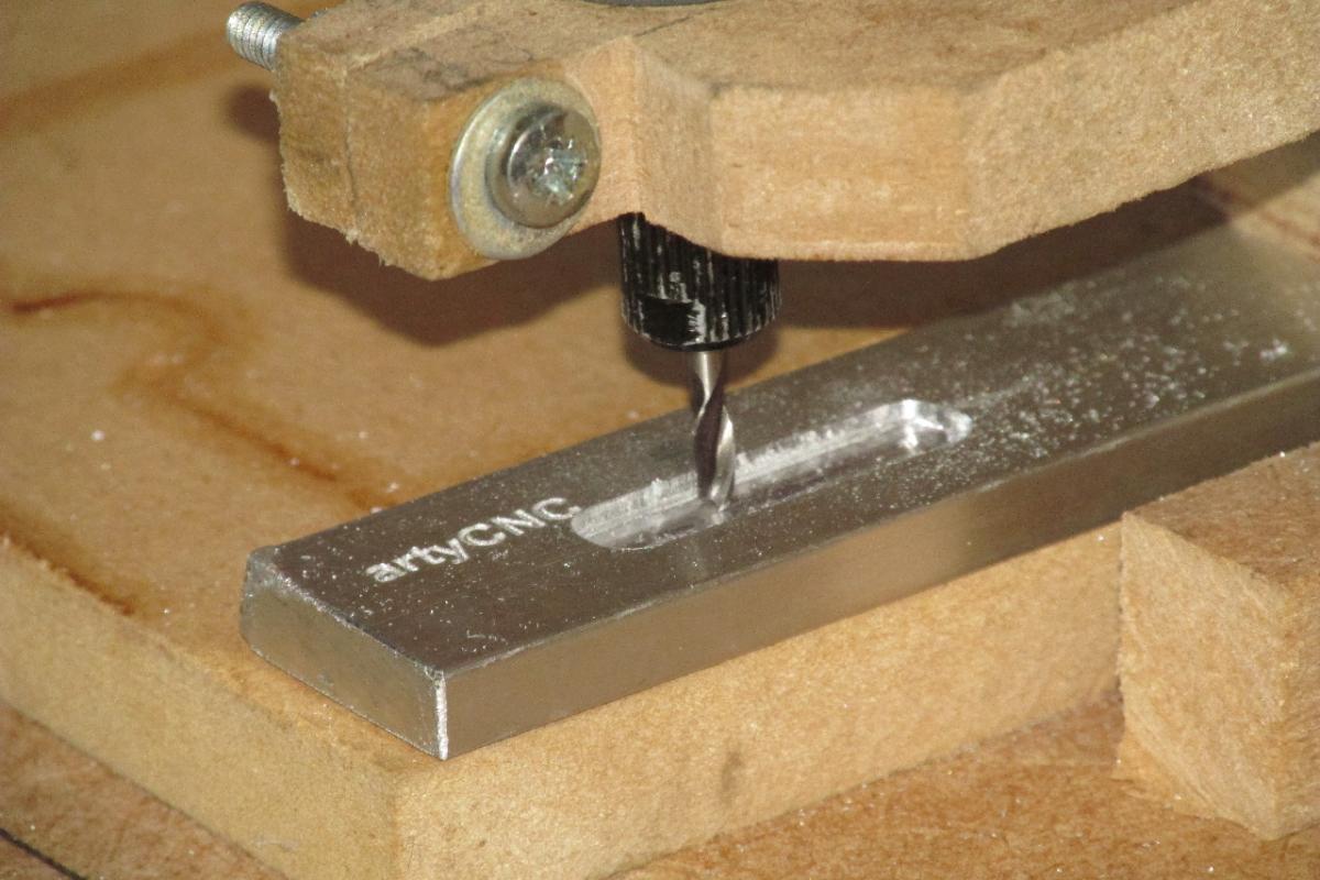
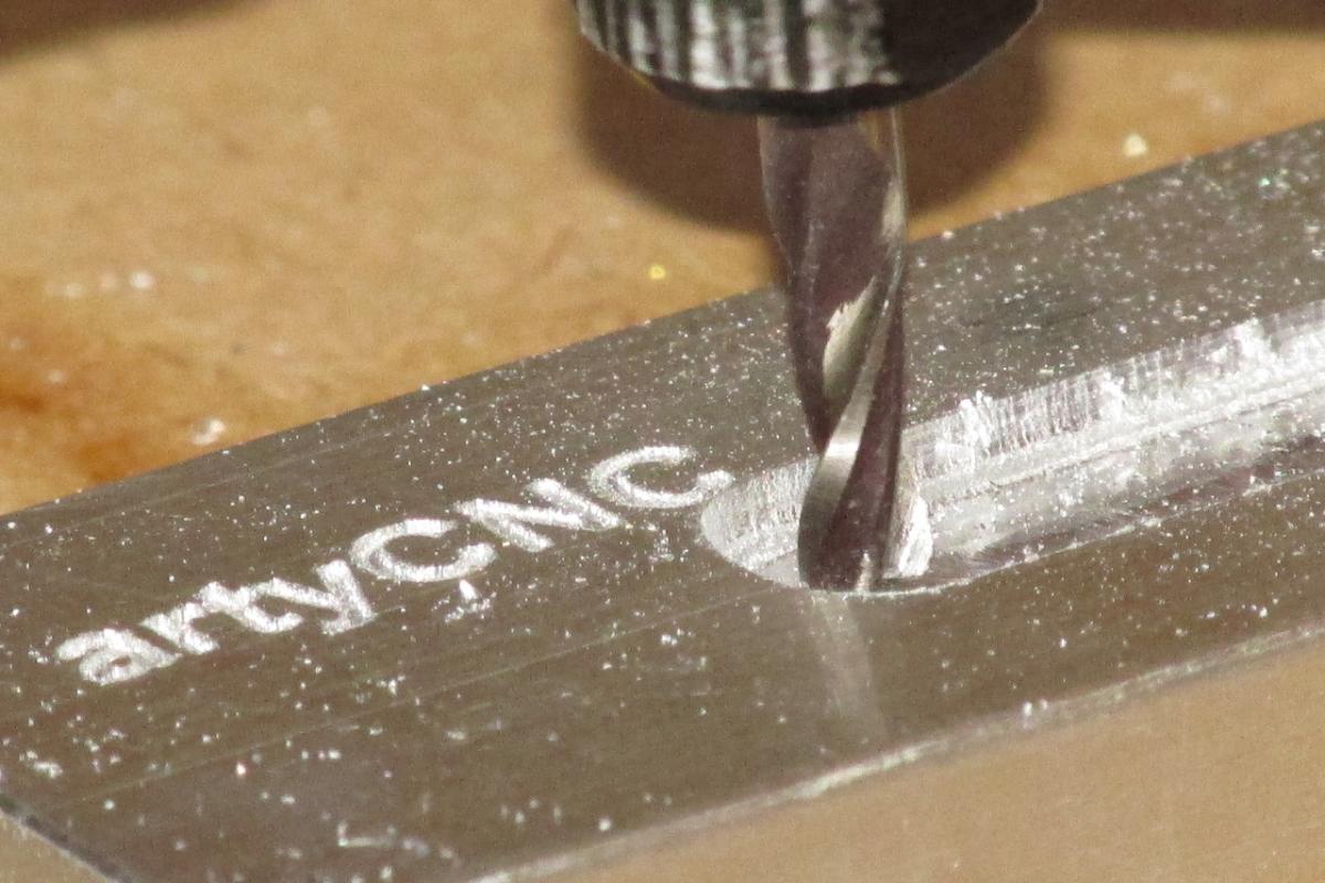
My first foray into machining Aluminium has met with partial success:-
Engraving, using a 0.1mm 10deg engraving bit came out perfect (see photos..). This was 3mm high text, engraved to a depth of 0.3mm.
Milling, however, threw up it’s own problems… The 3mm endmill I was using kept getting pushed up into the collet, no matter what spindle speed and feedrate I used. Also, at some point, both the X and Y axes missed steps and threw the whole cut out of line.
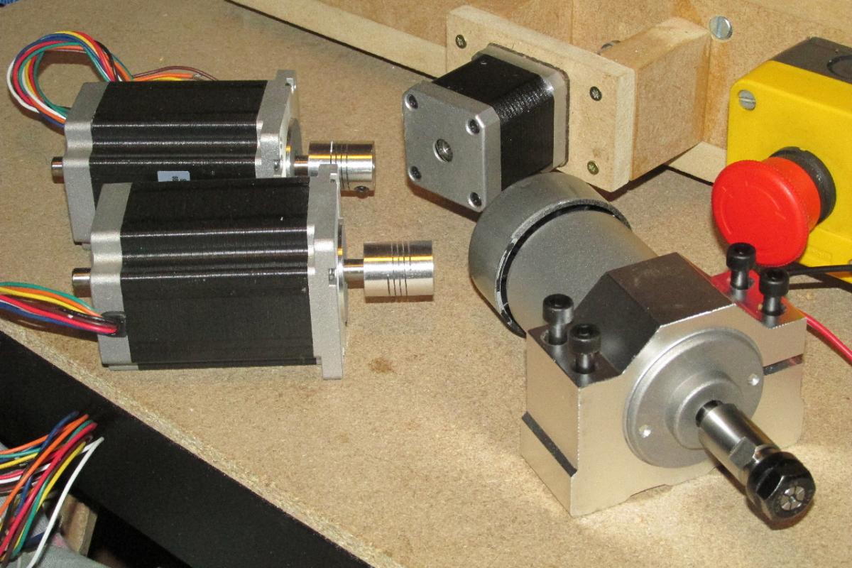
To address these problems, I now have a proper milling spindle on it’s way, and, starting with the X-axis, moving the whole gantry, a much heftier NEMA23 stepper. If the new stepper proves to give me much more accuracy (without missed steps) and a higher feedrate, I’ll replace the Y-axis as well. The Z-axis can have the stepper that is currently on the X-axis, which has slightly more torque than it’s existing one.
Looks very promising. If you manage to iron out the final quirks you have a great tool there
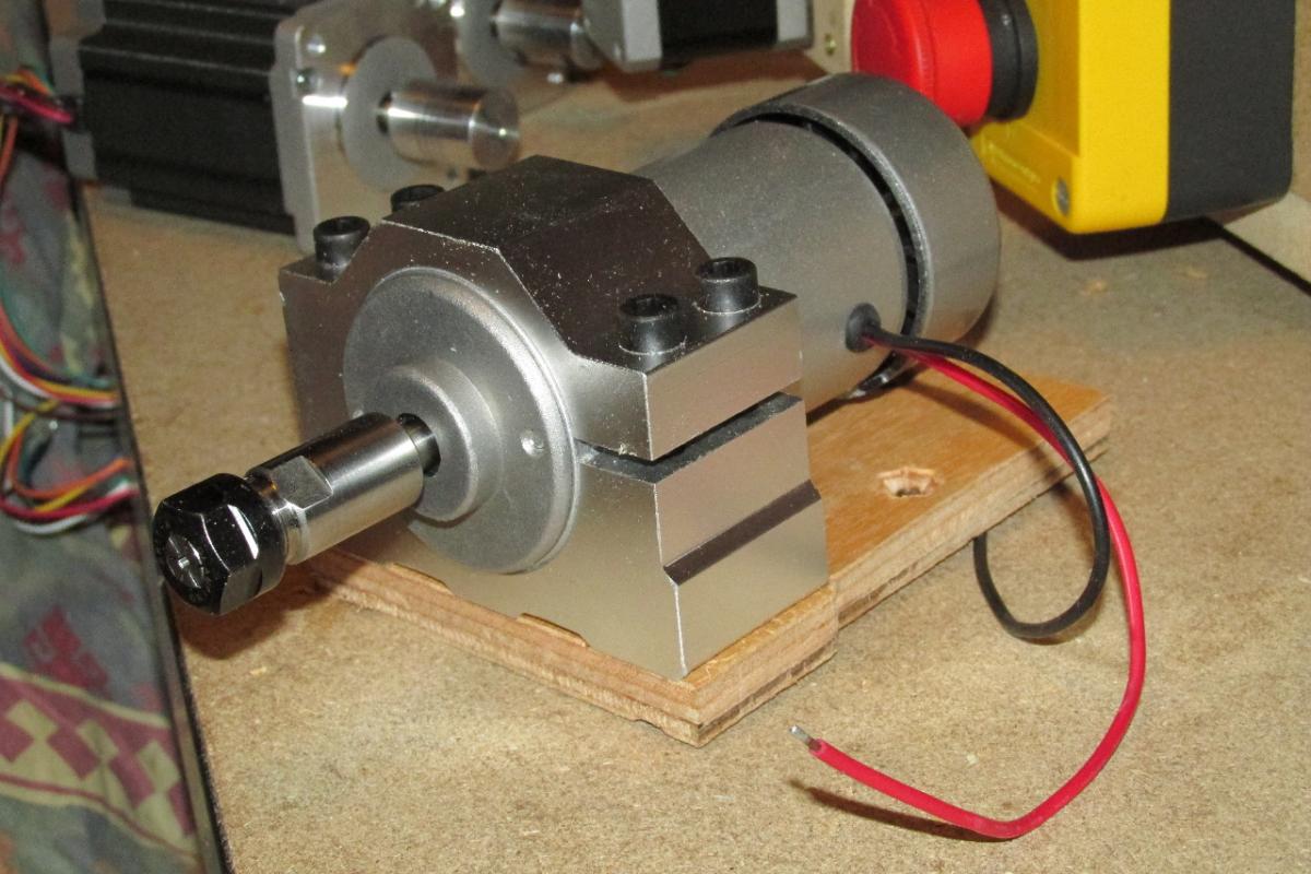
New upgrade parts have now arrived… hopefully this should make a difference to the speed of the machine, and stop the cutting bit getting pushed back up into the tool.
now making the new mountings for them… if a bit slowly !!
Nice! Hope there aren´t any skipped steps now! Please continue posting your findings, albeit I can´t yet build and especially operate one, it is very interesting!
Many greets, Peter
Yeah, this looks very promising - and interesting indeed! I have been thinking on and off about building a cnc myself, but it’s still a very intimidating thought!  Very nice work!
Thank you for your support and interest… It was a daunting prospect at first, but then, so is building your own synth from scratch. The processes involved are very similar, break it down to small sections… design, build, test… add on the next section… etc..
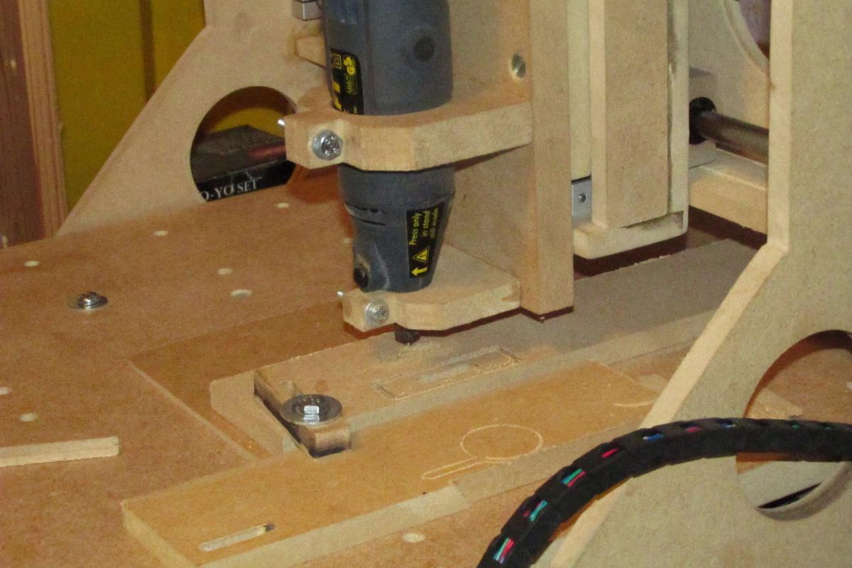
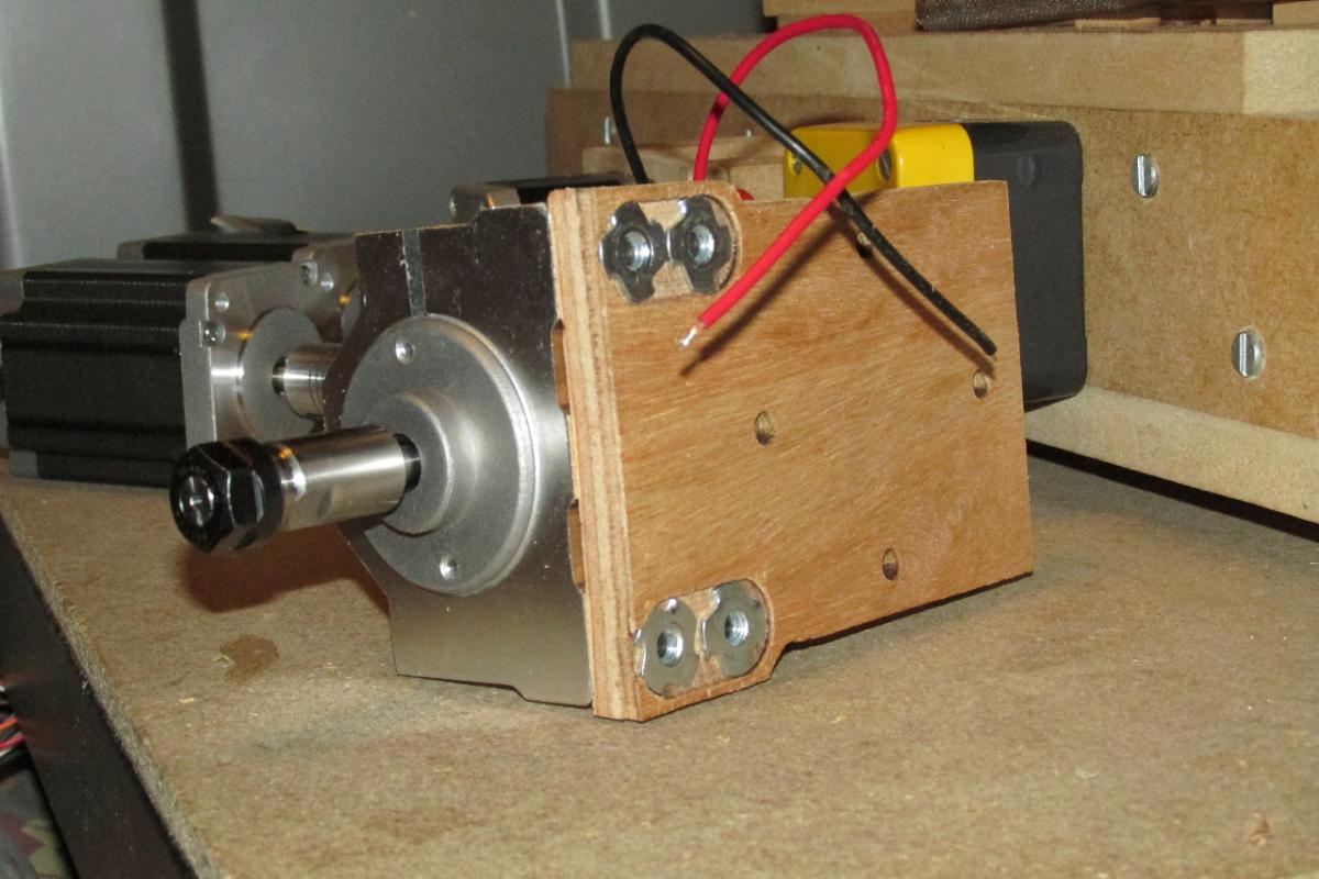
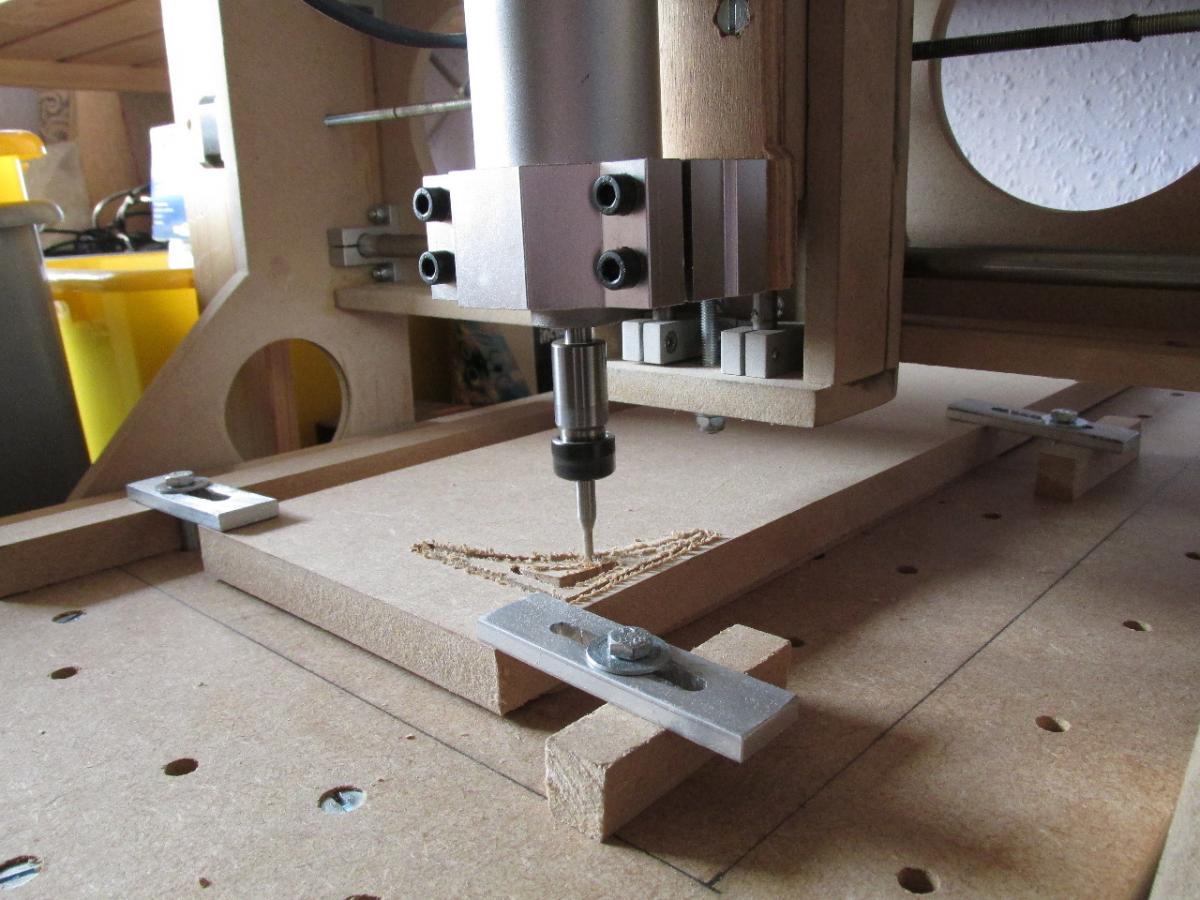
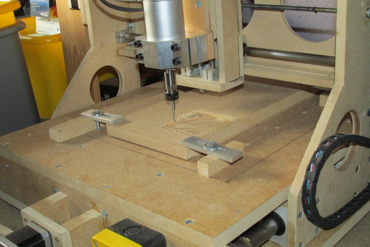
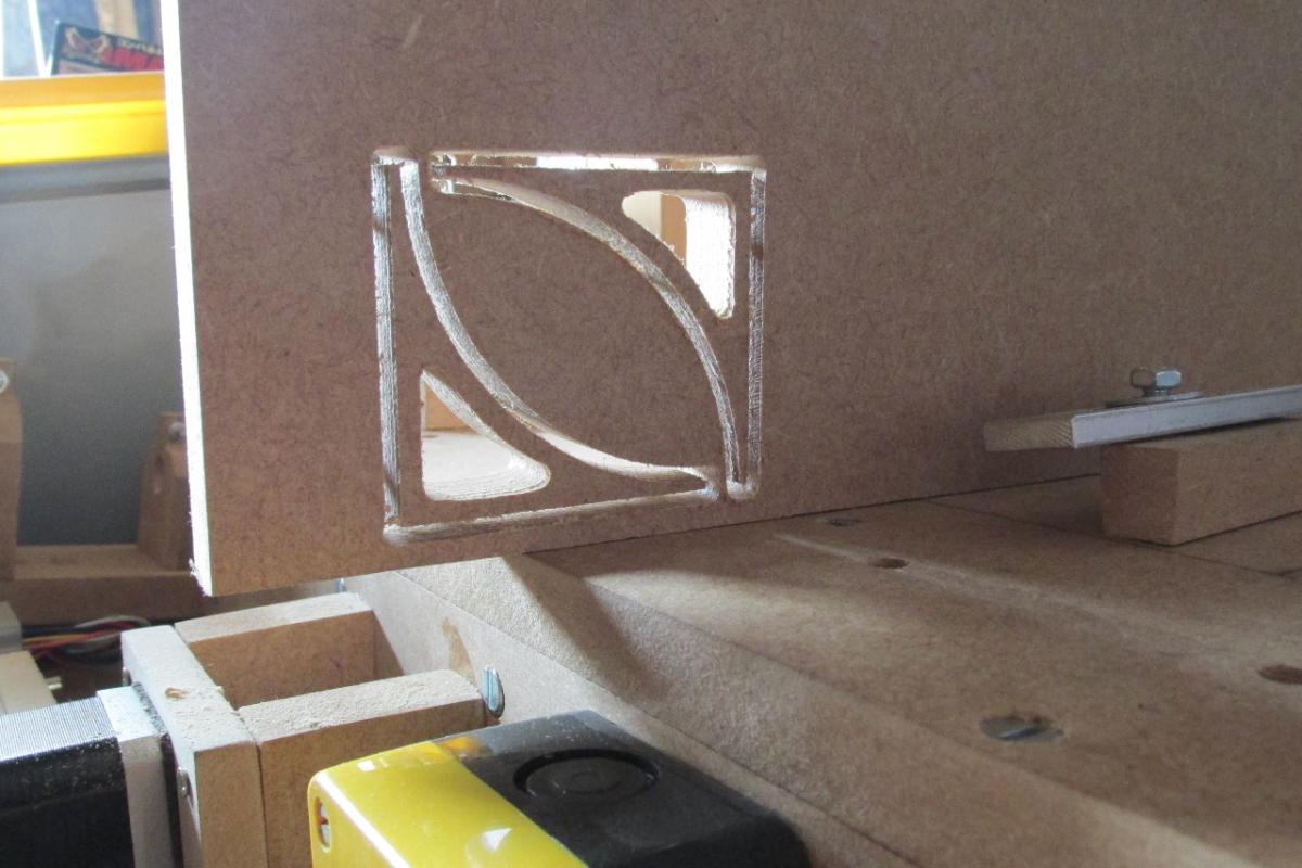
Anyway, got the new mount for the spindle done. I had to recess the T-nuts due to the clearance between the tool mount and the Z-axis frame being so tight. The holes and the pockets machined very well with the original tool, but it was having difficulty with the cutout, so I had to cheat a bit and stop the cut, then using the slot I already had as a guide, jigsaw it out completely and file the edges flush. Overall I’m pleased, as the most important parts were machined properly before the problems.
Photos show:-
wow… this is crasy/awesome/unbelievable… DIYer makes me dream everyday since i came on this forum !
Congratz !!!
UPDATE:-
Now the spindle upgrade is done, It’s so quiet that now I can hear all the other rattles and rumbles that the frame is making.
So… in addition to the motor upgrades, and re-designing the X-axis transmission, a bit more bracing is needed on the gantry. The most worrying is some lateral play along the X-axis which is causing a slight ‘twist’ around the centre.
I believe this can be solved with an arrangement of wire rope and pulleys to keep the gantry in a fixed orientation, in a similar manner to the rulers on a draughtsman’s drawing board.
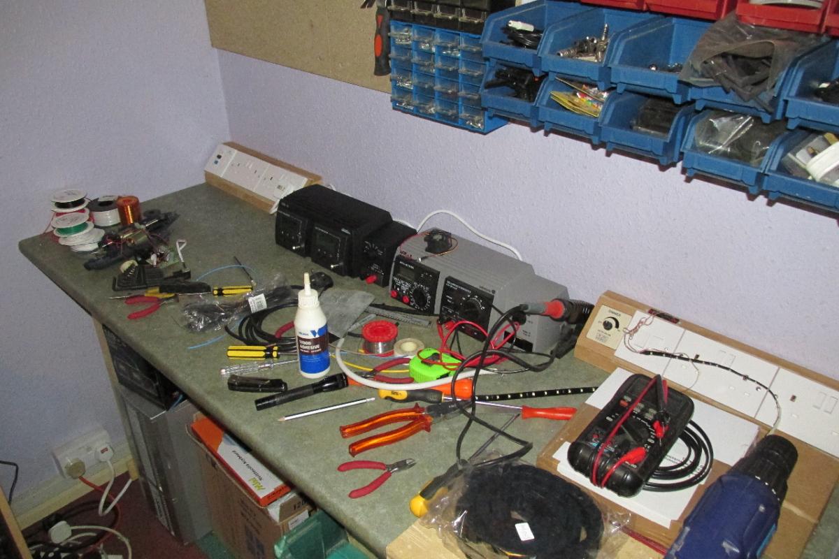
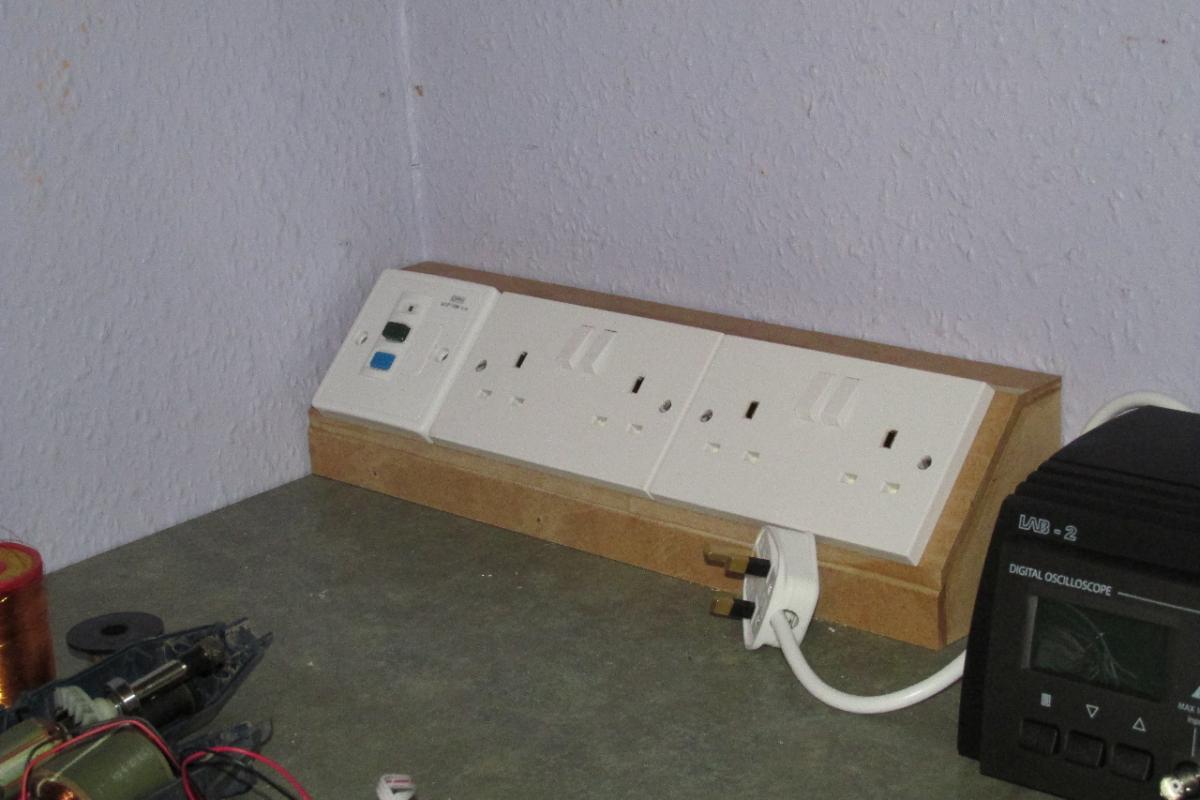
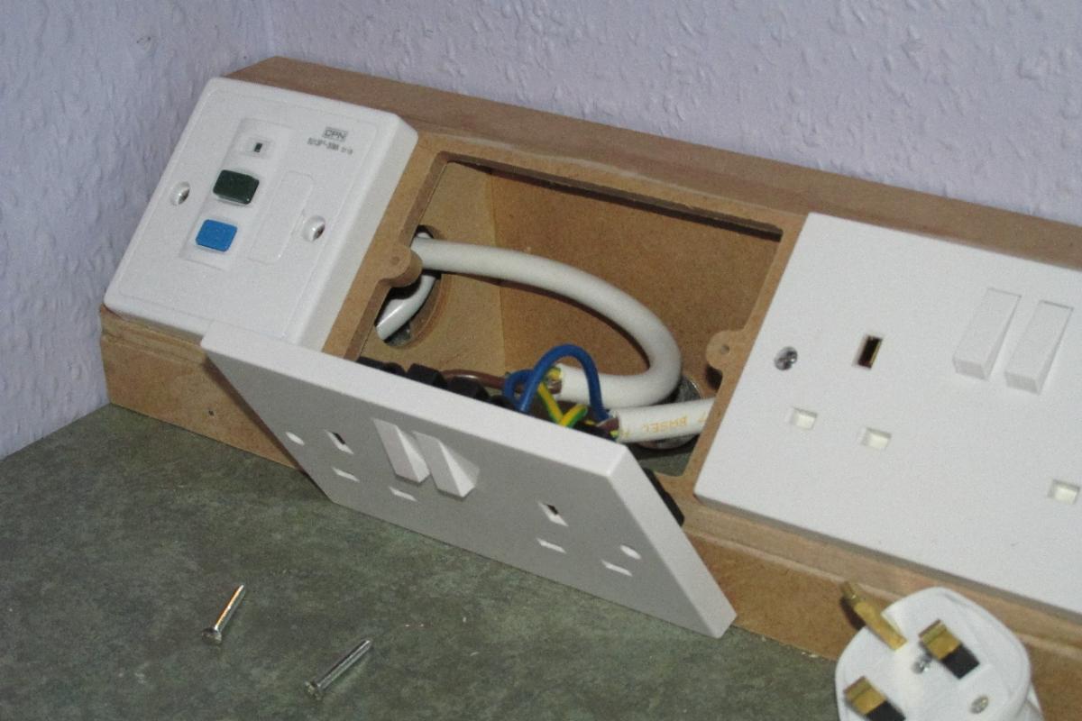
On the positive side… my first project made with the aid of the CNC is now built, fitted and working - the power ‘pods’ on my workbench.
note.. I had to chamfer the edges by hand, because I didn’t have a suitable tool for the CNC to do that.