Smart move! The little notches in the top left corner were meant to be for a diode jig but unfortunately I didn’t quite get the distance right.
Best of luck for the remaining parts.
Smart move! The little notches in the top left corner were meant to be for a diode jig but unfortunately I didn’t quite get the distance right.
Best of luck for the remaining parts.
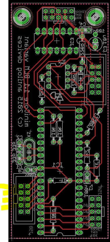
I’m finally done soldering the parts (except the sliders). Whew! I’ve installed the blm_scalar software on the PIC using an old core board. What unused AIN pins do I need to jumper on J5B? I can’t really tell from the pictures.
The instructions show the cable pin connections between the din8 connector and the minicore board on the blm. What about on the other side, between another din8 connector and the seq4 core? I’m still using a LPC17. What should that look like?
I’m finally done soldering the parts (except the sliders). Whew! I’ve installed the blm_scalar software on the PIC using an old core board. What unused AIN pins do I need to jumper on J5B? I can’t really tell from the pictures.
This view of the board has J5B on the rear. So four pairs of AIN should be jumpered to ground towards the middle of the PCB, the bottom-most is +5V and shouldn’t be shorted.
The instructions show the cable pin connections between the din8 connector and the minicore board on the blm. What about on the other side, between another din8 connector and the seq4 core? I’m still using a LPC17. What should that look like?
Do you have the Quad IIC installed? If not, you need to provide another MIDI connection (the input of which should be optoisolated). You can supply power via the DIN or else by using the extra case holes for a separate power connection/regulator.
Do you have the Quad IIC installed? If not, you need to provide another MIDI connection (the input of which should be optoisolated). You can supply power via the DIN or else by using the extra case holes for a separate power connection/regulator.
I’m using the LPC17 core which has midi connections on the board. It sounds like I need to dedicate a midi i/o pair to the BLM. I have an old IIC_MIDI board (http://www.ucapps.de/mbhp/mbhp_iic_midi.pdf) that I’m not using. Can I use this board to connect to the LPC17 core and BLM? It looks like J2 on the IIC_MIDI board connects somewhere to the core. I’m not sure how the midi board is wired to the DIN. The build guide shows 6 connections between the minicore and DIN on the BLM. I’m guessing I’ll also need 6 connections between the seq4 and DIN.
Some of the pins on the left header are connected (1&2&3&4, 9&10). Should I just tie these pins together by soldering underneath the header?
May i know all about the circuit details and the hardware components used here?
What are the deigns of the circuit and the PCB and your firmware?What specifications this hardware consist and what are its applications?
What an interesting post! If you like I can sell you one of the bugged circuit boards. The potential applications are for floor tiles, doormats, frisbee etc.
I’m using the LPC17 core which has midi connections on the board. It sounds like I need to dedicate a midi i/o pair to the BLM. I have an old IIC_MIDI board (http://www.ucapps.de/mbhp/mbhp_iic_midi.pdf) that I’m not using. Can I use this board to connect to the LPC17 core and BLM? It looks like J2 on the IIC_MIDI board connects somewhere to the core.
The board I was talking about is this one:
http://midiboxshop.bigcartel.com/product/quad-iic_midi-module-board
http://www.midibox-shop.com/quadIIcMIDIR2.html
As you can see, it generates 4x MIDI outs from the IIC buss. Notice the extra circuit is dedicated for the BLM and just optocouples MIDI IN (3) and provides a pullup for MIDI OUT (3). It conveniently has a DIN8 connector right on the PCB. So I guess if you wanted to use your PCB, you would ignore the PIC 16F and connect up J4 on the IIC to J5B on the Core. Or the opto circuit could be built on veroboard. I’m not too sure if it should run at 3V3 or 5V. Maybe try the lower voltage and see if the MIDI transfer is stable. It seems sensible to power the optocoupler at 3V3 as this should (?) levelshift the 5V MIDI IN signal from the BLM. Likewise, any 3V3 MIDI IN signal entering the miniCore should be level shifted up to 5V. Please correct me if I’m wrong!
I’m not sure how the midi board is wired to the DIN. The build guide shows 6 connections between the minicore and DIN on the BLM. I’m guessing I’ll also need 6 connections between the seq4 and DIN.
Just imagine this connector as 0V, 5V (perhaps not connected if you power the BLM separately), and the standard MIDI connections MI+, MI-, MO+ and MO-. Only two connections are “data” that need to connect to the Core, the other two are a pull up for MIDI OUT and a “virtual ground” for MIDI IN. But I admit I’m not well versed in the lingo of MIDI current loops!
Some of the pins on the left header are connected (1&2&3&4, 9&10). Should I just tie these pins together by soldering underneath the header?
I suggest to use a 10 pin ribbon cable and connect the 4*0V and 2*5V to the DIN8 panelmount socket to decrease resistance in the thin wires. These connections are made on the miniCore PCB itself, so no need to add more solder. But if you’re like me, sometimes when heating up large ground planes the solder flows a bit thick and bridges a few common pins. That’s okay too.
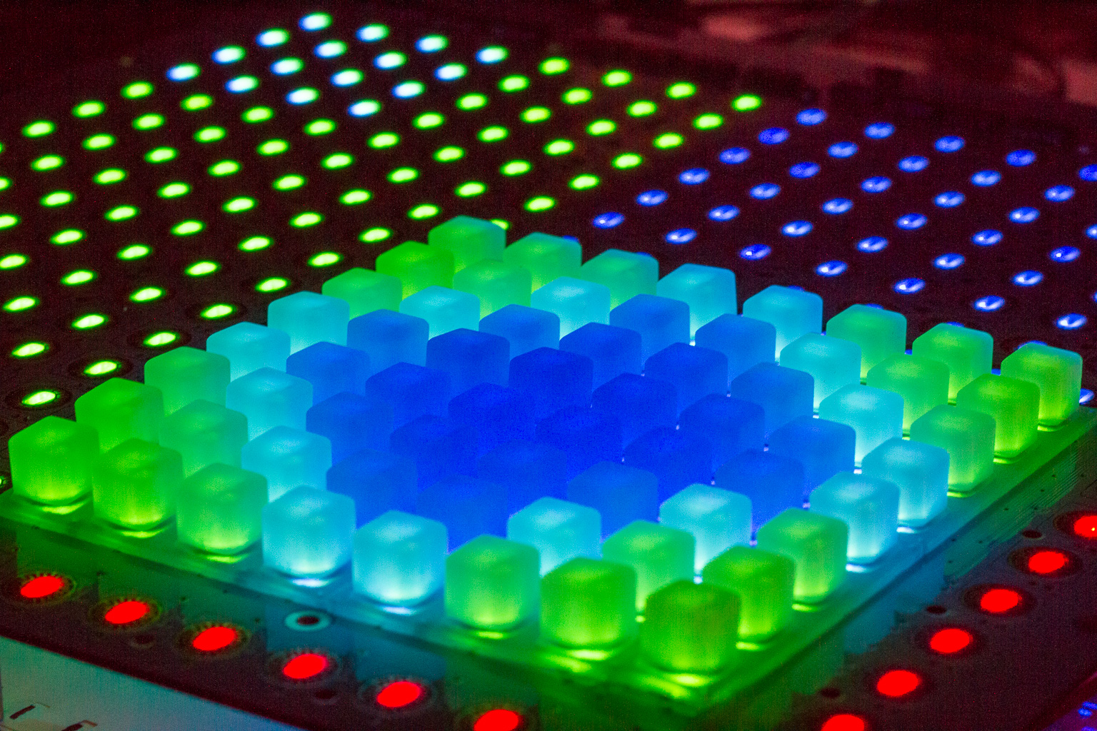
It’s working! I powered up the blm from a bench supply. These are the best kind of holiday lights. 
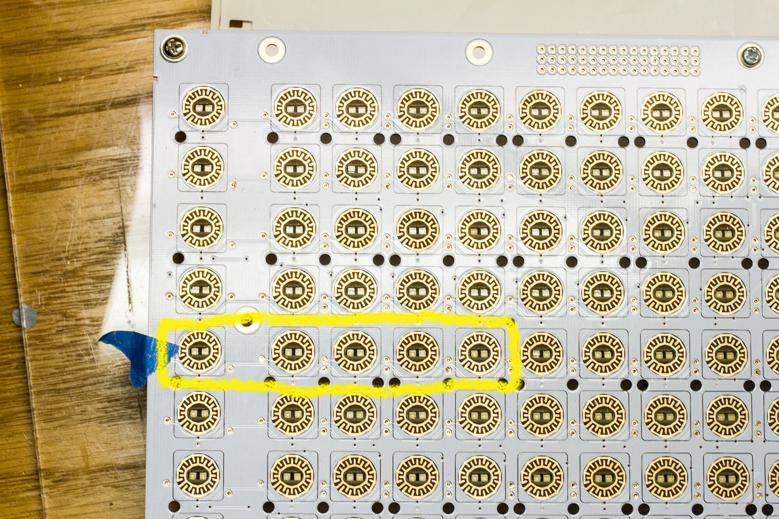
One small issue: a segment of 5 buttons isn’t working. I’ve touched the LED’s and diodes in this group looking for a bad joint. I’ve also touched around IC5 and R5. I’m not sure where to look next. Here’s a screenshot showing the non-working buttons/leds:
Pretty sweet!
For the non-illuminated 5, first check the diodes are soldered correctly. Then do the LEDs have the correct polarity? The main grid and extra column are only common from the cathode side. When viewed from the back, the lower contact on the LEDs should show continuity for all of these 5, in fact the first 9 cathodes should all be connected in a row. The second 8 of a row are driven through a separate transistor.
From the topside, is there a slight scratch on the trace just to the inside of the right side of your yellow box? If this trace is somehow cut, please connect cathodes on the 5th and 6th column on the same row.
From the topside, is there a slight scratch on the trace just to the inside of the right side of your yellow box? If this trace is somehow cut, please connect cathodes on the 5th and 6th column on the same row.
You must have eagle eyes. You were right, there was a small scratch on the trace. I soldered in a little jumper on the bottom and now that section works. Thanks!
The board I was talking about is this one:
http://midiboxshop.bigcartel.com/product/quad-iic_midi-module-board
http://www.midibox-shop.com/quadIIcMIDIR2.htmlAs you can see, it generates 4x MIDI outs from the IIC buss. Notice the extra circuit is dedicated for the BLM and just optocouples MIDI IN (3) and provides a pullup for MIDI OUT (3). It conveniently has a DIN8 connector right on the PCB.
Ah, I didn’t know about this board. I’ve got an old IIC_MIDI board and two of the newer MIDI io modules (http://midiboxshop.bigcartel.com/product/midi-i-o-module-board). There’s too many of these midi boards available to keep them all straight.  I just ordered this quad midi board from Tim.
Glad to hear it’s all glowing now!
For the QuadIIC, be careful with the DIN8 connector that you order as there are two different pin configurations. I ordered twice from Mouser thinking it was my mistake, but their description was wrong. Hopefully they’ve updated it. They can be had on eBay, if I remember the seller was based in the UK.
Yeah! congratulation Jbdiver!
Just imagine this connector as 0V, 5V (perhaps not connected if you power the BLM separately), and the standard MIDI connections MI+, MI-, MO+ and MO-. Only two connections are “data” that need to connect to the Core, the other two are a pull up for MIDI OUT and a “virtual ground” for MIDI IN. But I admit I’m not well versed in the lingo of MIDI current loops!
Can you describe the pin assignments for pins 1-6 on on the DIN? In other words, which specific pins are used for 0V, 5V, MI+, MI-, MO+ and MO-?
Also, I picked up the adafruit verter board. What holes on the verter board did you use to mount it to the main board? I see holes labeled 5, G, PG, PS, G, EN, Vin. My guess is that I shouldn’t use the holes labeled 5, G, or Vin.
Can you describe the pin assignments for pins 1-6 on on the DIN? In other words, which specific pins are used for 0V, 5V, MI+, MI-, MO+ and MO-?
The connections are listed here but at least for me they are very confusing. It’s exactly the same on the Quad IIC.
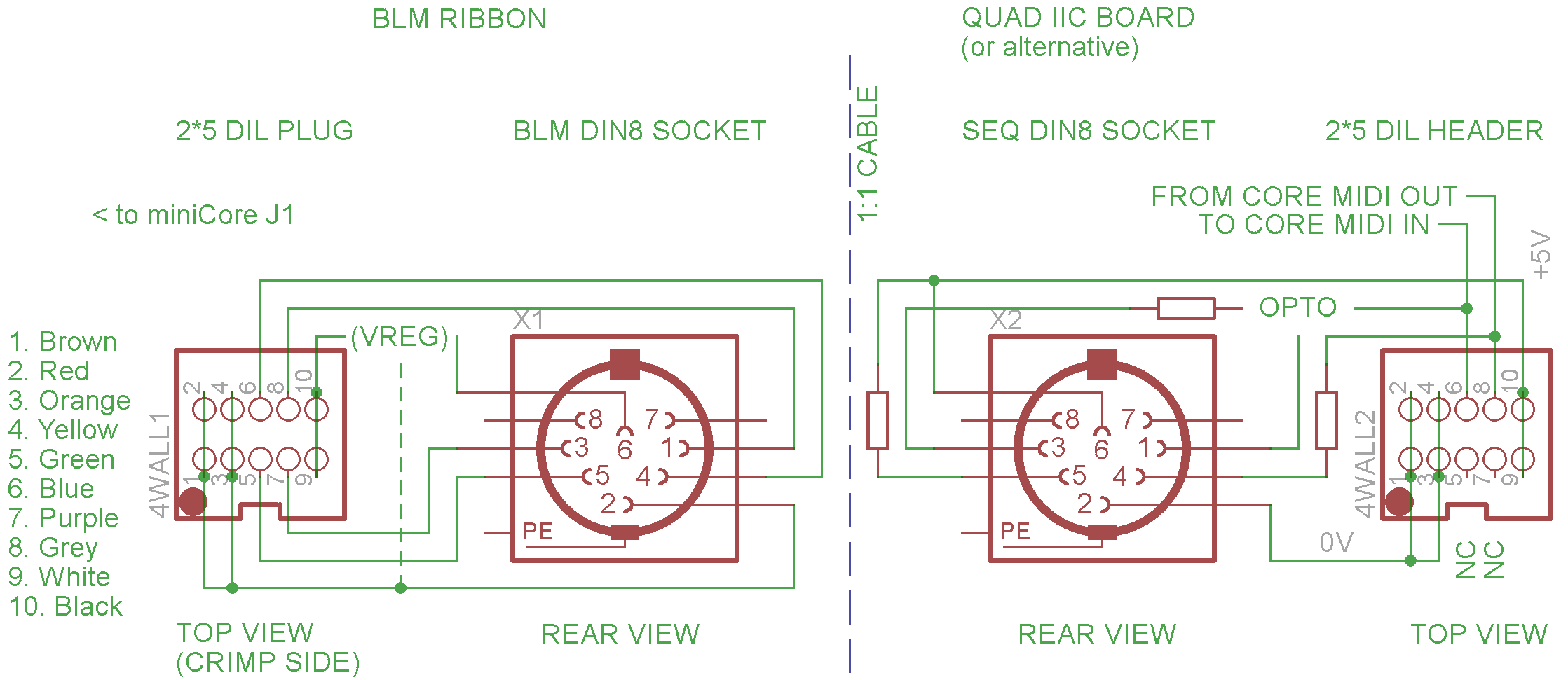
So, I’ve redrawn the diagram:
I guess it’s complicated because one box’s MIDI out is the other’s MIDI in. The connections listed have common power on pins 6/2.
SEQ side: MIDI out from the Core is current limited then goes to pin 4. Pin 5 is the pull up to +5V. MIDI in to the Core arrives on pins 1 and 3 and goes to the optocoupler. The optoisolated signal then goes to the appropriate MIDI in on the Core.
On the BLM side, if the connections are crimped by colour/order as I’ve mentioned, just plug the right way into the miniCore and you’re done :). (The order is switched relative to the SEQ side to connect SEQ MIDI OUT <-> BLM MIDI IN and BLM MIDI OUT <-> SEQ MIDI IN.)
Also, I picked up the adafruit verter board. What holes on the verter board did you use to mount it to the main board? I see holes labeled 5, G, PG, PS, G, EN, Vin. My guess is that I shouldn’t use the holes labeled 5, G, or Vin.
That’s exactly how I mounted it; long side of a single 4 pin header to the muck area (raised up by the plastic on the PCB front side), short side to the VERTER PG, PS, G, EN.
SmashTV sells only PIC18F4685 in his shop.
Will this work as a replacement for the 18F4620 that is used for the miniCore?
Yes, it will work as well with the same .hex file (no need to re-compile the application, since MIOS8 contains the PIC18F4685 specific parts).
Best Regards, Thorsten.
i’ve done the test last month it works…
Thanks, I added the PIC info to the OP.
thanks!
HI all,
looks like I’m almost there. From what I have seen in the power-on test, I have 3 rows not working. I’m guessing this is down to a cold solder joint or a short. They are (going by transistor Q number): Q29, Q19 and Q22. Would a cold solder joint some place be the top of the list of culprits?
Are the rows completely unlit or only half? If it’s the latter then it could be related to the transistors.
Bases (bottom left) of the transistors connect to the resistor networks:
Q29 connects to pin of RN14, Q19 to pin 14 on RN10, Q22 to pin 10 on RN10.
Emitters (bottom right) connect to ground, but other pins shouldn’t. Check if there’s a short to ground.