I thought long and hard about what LEDs to use. Yes, the package size is similar, but look at the brightness: 45/35 mcd. Recommended is more like 300 mcd. And the green is 571 nm, more of the yellowy-green. (Look also at the forward voltage, true green is always around 3.3V.)
When we love , we don’t count… (french expression)
tack solder is cool… fix/align make me scream!
i start soldering leds with a classic 30w iron and i go to supplier buy a real iron ESD temperature programmable… (260°)…
can’t wait for the 1n4148!
Can happen. Start with the R1 bridge, you may have a small short if you scratched some soldermask off. Check every cap/ pins for 5V and pin 16 of the 10k resistor networks.
Thanks for the tip, originally I had 5 extra RNs in.
For the transistor/resistor pairs, what short do you mean? Short to ground? You might have to upload photos. Note that the bottom right transistor pin should be connected to ground. All 74HC165 inputs have a pullup to 5V. Please check carefully around this pin, is the solder mask scratched? If you try to reflow the solder it can help.
sorry for the debug…
i take all the time to build cool it with optimum conditions… more than 30hours (Thorsten is a god , a robot or the god of robots to manage it in 15h)
since the problem i reflow many times…!
for the resistor/transistor pairs:
there are a shortcut between each resistor pad (resistor was 0.2 ohm value) without the components short is present! no solder mask scratched
for the 74hc165 pin 6 is shorted to ground or 5v because i’ve got a short between 5v and ground (when mesuring between 5v and ground at J3: 0,2ohm)
i’ve change this IC and it’s the same…
Okay, well I’m on holiday at the moment, so I won’t be able to remote debug very easily. Even with a short on this resistor it would only kill that particular section and not the whole 5V line.
5V short could be anywhere on the board, not necessarily at that IC. Check the vias and mounting holes too.
2 mA per led if there are all illuminated (that will never arrive in normal use) result 1156 mA so 1,2A (i can’t mesure it cause bugged)
1.2A is security value and not the real consumption wich will be less than 1A.
i receive the case today , beautifull and look very strong!
I don’t have my unit here to test, it’s at a friends awaiting a few modifications (my case had fewer standoffs so needs mechanical strengthening). TK. should be able to give you an idea of current draw with all LEDs lit, probably he has a nice bench supply running :).
Perhaps a small caution to check the board for errors before starting. They have been electrically tested but there’s a remote possibility of unmasked ground plane which could give a short if covered with a lot of solder. I have a few spares here which I will go over carefully when the light is better, will let you know if I find anything.
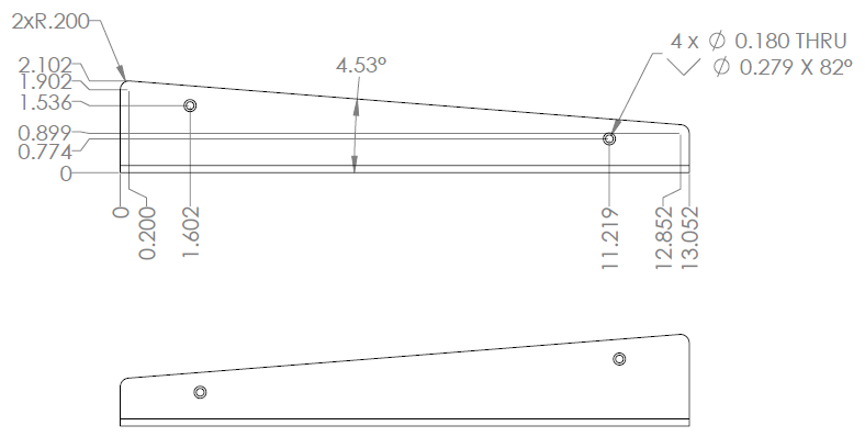
Here are a few images of the side in case you want to make wooden end cheeks. Dimensions are in inches, please check them against your case to be sure.
EDIT: suppose you could make some metal flange rack ears too! Oh, these screw threads are 6-32 and all screws are stainless steel so the aluminium parts should last for a very long time.
I’m going to be ordering the button spacer in the next week or so. Is there anyone in the UK that also needs the spacer so we can split the shipping cost?
Note that I added some enhancements & fixes to the MBSEQ firmware while working on this demo (demos are always a good possibility for me to doublecheck that everything is working as expected!). The changes are already in the SVN repository and will be released soon.
Note that I added some enhancements & fixes to the MBSEQ firmware while working on this demo (demos are always a good possibility for me to doublecheck that everything is working as expected!). The changes are already in the SVN repository and will be released soon.
Best Regards, Thorsten.
TK.: very nice! It looks like the slider implementation is very good. I guess you kept the longer sliders in? This will be a personal preference I suppose. An idea I had was to make or buy some silicone covers to use as slider caps. This might make them a bit more ergonomic and also act as diffusers for the LEDs which can be quite bright.
I take it that there’s no issues with the case? Stability (i.e. no PCB flex) is good with the extra standoffs? Are all M2 grub screws installed? Do the bottom feet work?
Next up will be to connect up extra expression pedals, CV inputs etc. :) (another DIN connector?)
So just to confirm: quad IIC blm port connects to J5B on the STM32F4 core?
The BLM/quad IIC schematic always gives me a headache :). My approach was to harvest old PC cables (with single or dual female pin sockets, could also crimp new ones) that connected all of the front switches, LEDs etc. to the motherboard, and join them with an IDC10. I’m still using the F1 Core, but luckily I have a breakout board which also separates MIDI IO 3.
If you have an older Core8 you can always swap out this for the miniCore during testing, just use temporary clips on the MIDI outs. You need to supply power to the BLM, and please don’t send data without the main board powered up.