Been having enough fun with the seqv4 I built 2 years ago that I wound up buying a Neutron to try semi-modular which in turn led to me starting to build a full modular system.
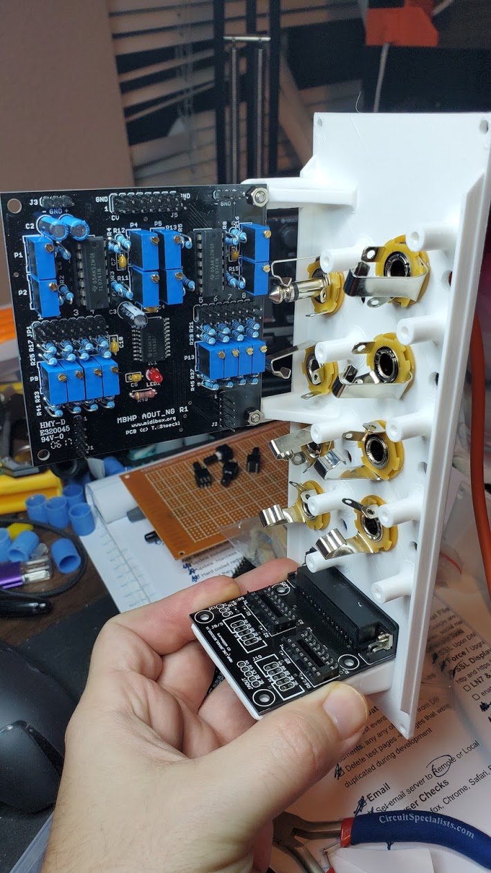
I had bought an aout_ng board from modular addict when I bought the boards for my seqv4 but since I didn’t have anything that used CV at the time it just sat in a box. Now that I have enough of a modular together to start doing something with I’m really wanting some CV out on my sequencer so ordered up the bits and built the aout_ng board and ordered a set of line driver boards which I built up so I can put the outputs in modules.
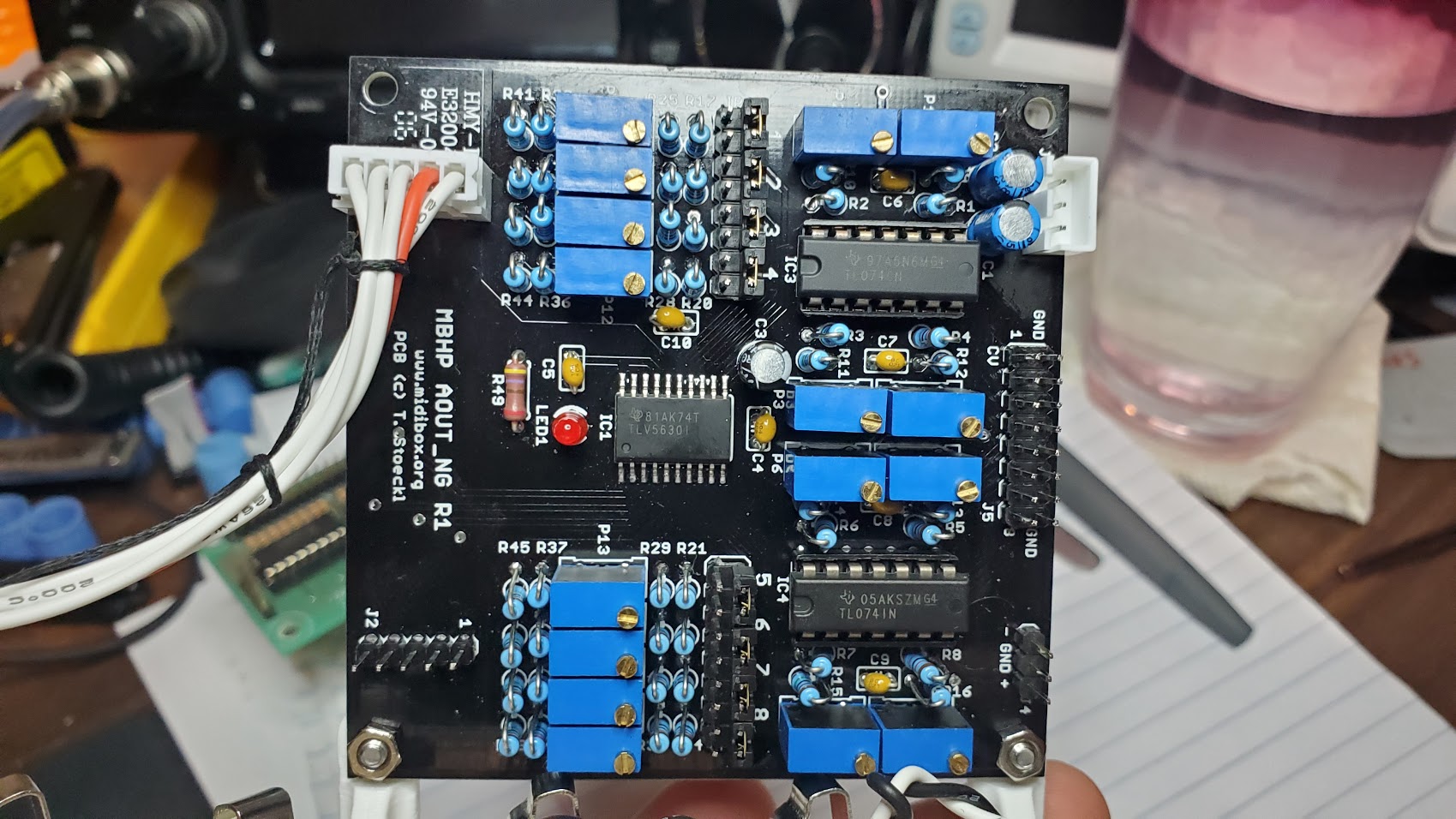
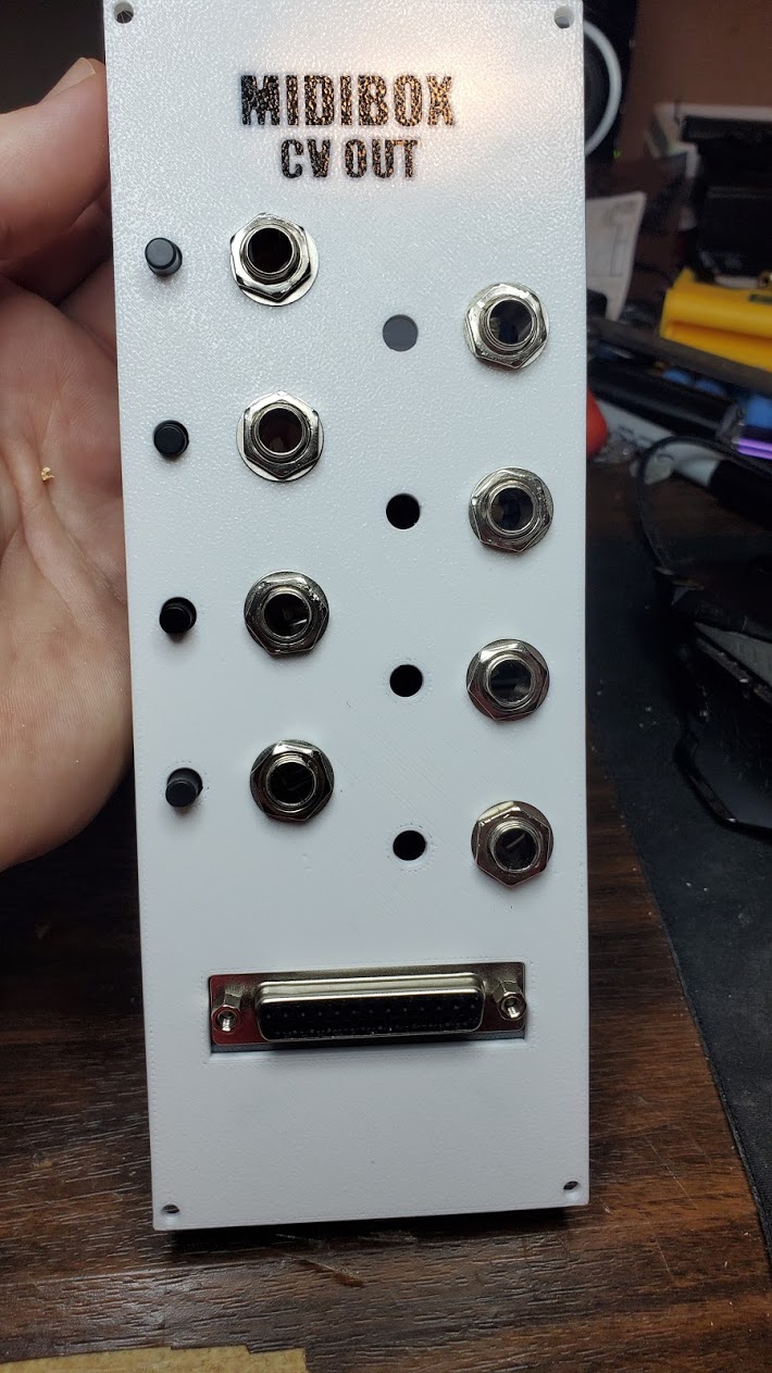
I’m mostly building my modular on the cheap with stripboard circuits and 3D printing panels, so that’s the approach I took for my CV outputs as well. The push buttons are to select normal/bi-polar but for now I just have jumpers for normal to start simple. I’ve also only wired up the first 4 outputs to jacks so far.
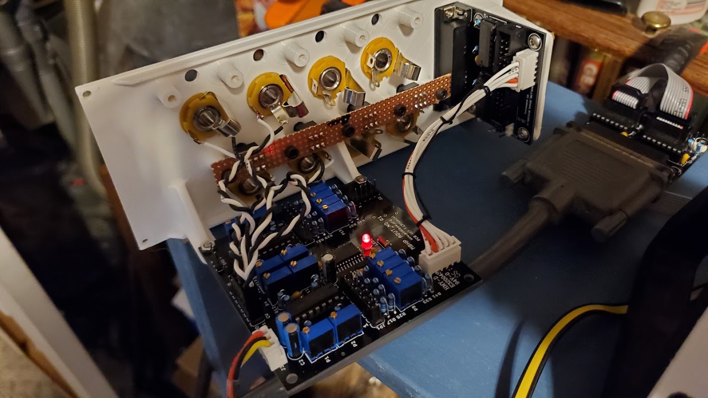
I’m pulling +/-12v off my modular power supply and have confirmed +/-12v on the appropriate pins of the TL074’s. Note - I used JST-XH connectors for power and J1 so I couldn’t mess up and hook anything important up backwards.
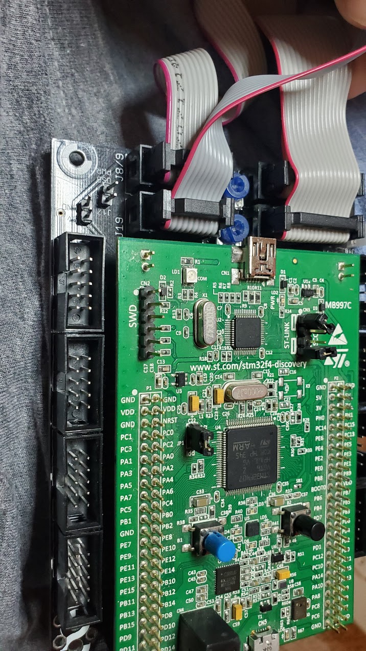
I had been powering the sequencer over USB…but found with the line drivers connected the current draw was more than the Disco’s regulator could handle and my LCD’s would loose contrast so I switched to my lab supply at 5v and now things seem to run much smoother and the LCD’s look better across the board.
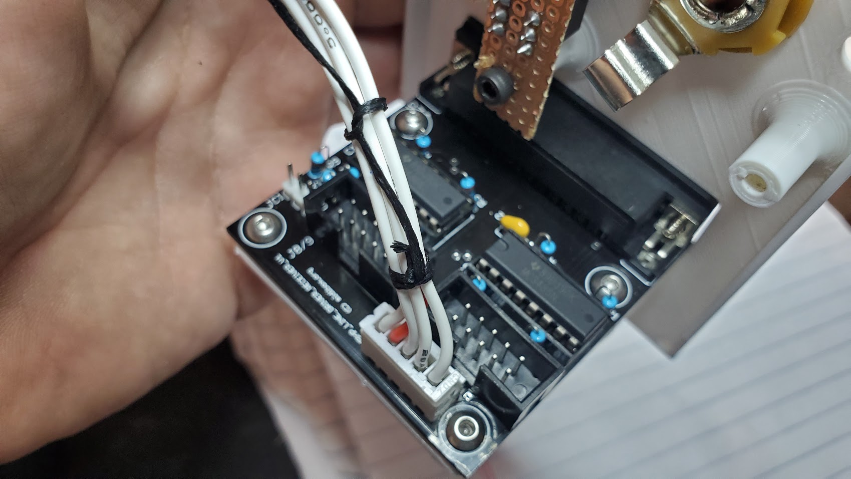
I also make a mistake on my J19 jumper from the STM32 to the line driver TX and initially had one of the connectors backwards. I figured that out and fixed it…and it seems the line drivers have survived as I’ve been able to use the testaoutpin in mios studio to confirm that the line drivers appear to be functioning. Though I’m a little confused as the help for testaoutpin says it will set the pins to 4v but when I run the command it says it’s setting it to 5v. Measuring right at J1 I see about 3.7v - 3.8v though…sometimes I do see 4v. Measuring at the DAC I see about .2v less than what I read at J1 but I do see the voltage change with testaoutpin commands.
But I only see 0.033v or less out on the outputs whether I use the caliaout command through studio or if I use the menus on the sequencer. And changing the trimpot makes almost no difference.
I haven’t tried wiring up a DOUT yet … I still have a few old ones (R2’s) from smashTV that I never built that have been patiently waiting almost 15 years for me to use them…so I did solder one up tonight (I’m going to want some gates anyway!) but won’t have time to wire it up until tomorrow. And I’m half tempted to just order some new R6 boards anyway since I like the jacketed 10 pin connectors more than the old pin headers :)
Did I damage something when I had the reversed connector on J19? It seems like the DAC may not be working…I haven’t looked closely at the schematics yet but it doesn’t seem likely that that would have fried the DAC. Seems more like it would have damaged the line driver chips if anything. And In fact I ordered replacement line driver chips just in case since initially I thought I had done just that. - though now they appear to be functioning and I’m wishing I had ordered a new DAC instead.
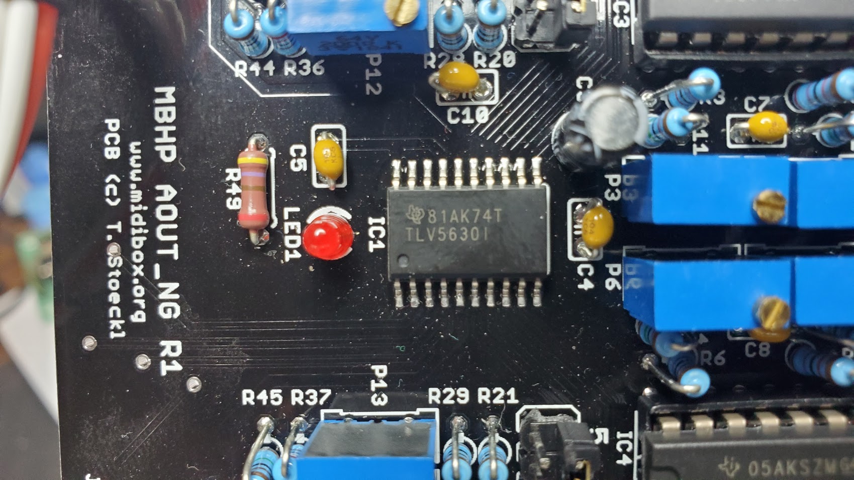
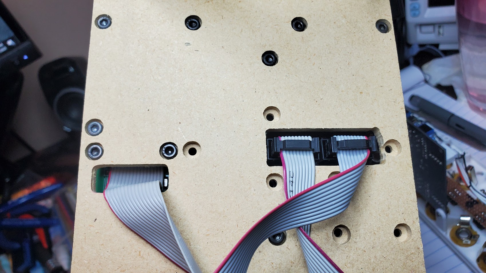
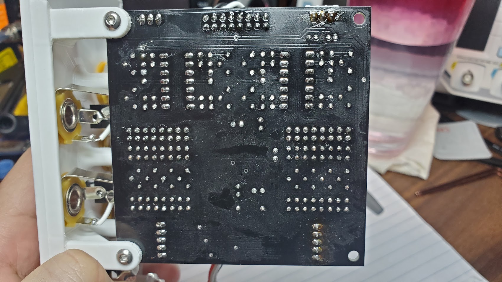
Photos of just about anything releveant I can think of attached. Note - what looks like it could be bridges between pins 12-14 of the DAC are just reflections on the flux residue. I’ve checked it under a magnifier and there are definitely no bridges on there.
Am I missing something that should be obvious…or even something less obvious? Or do I need to order a new TLV5630 at this point and break out the hot air station?