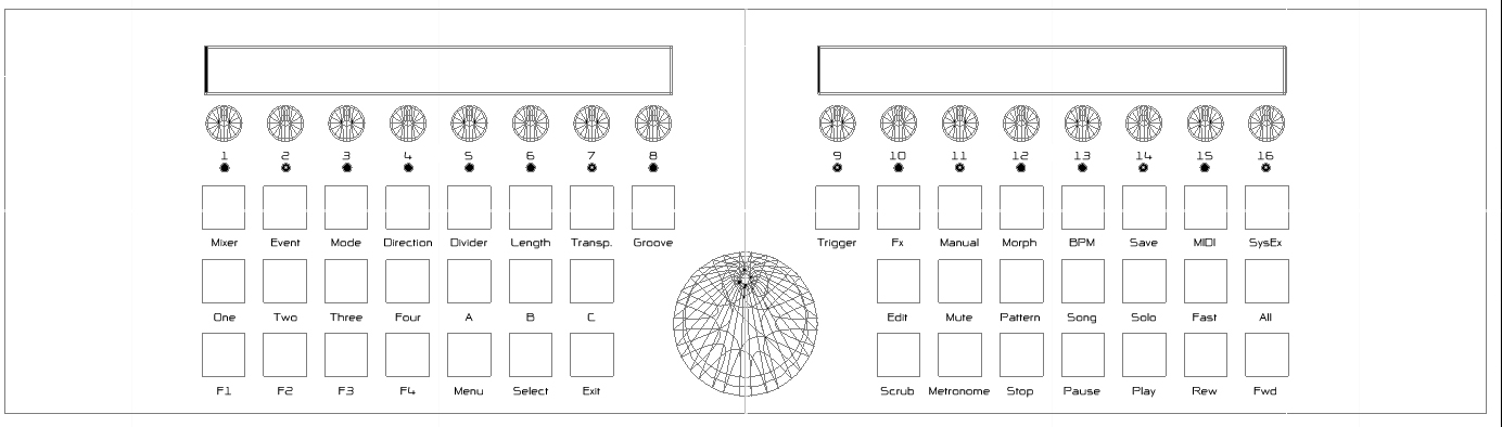
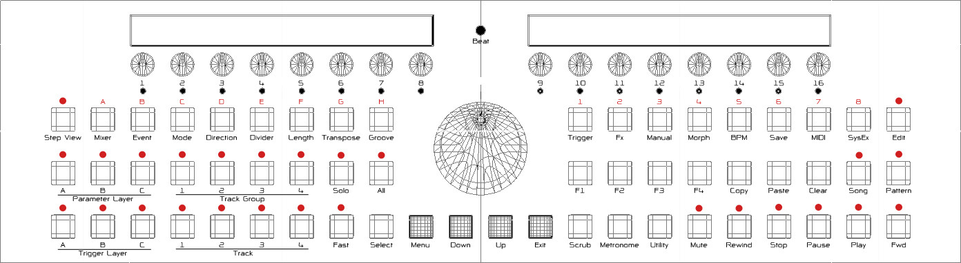
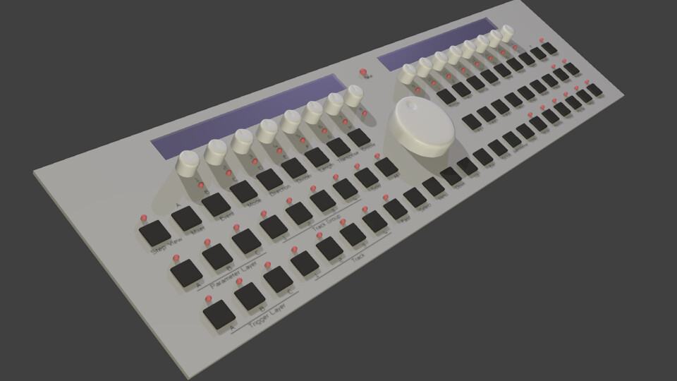
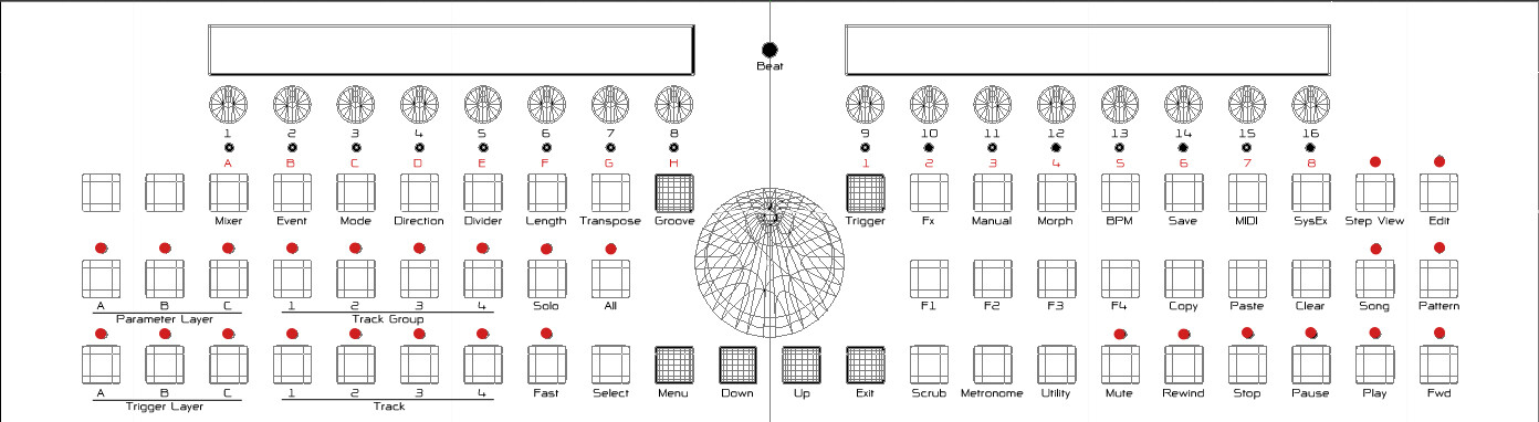
I’m using a combined LED and switch matrix.
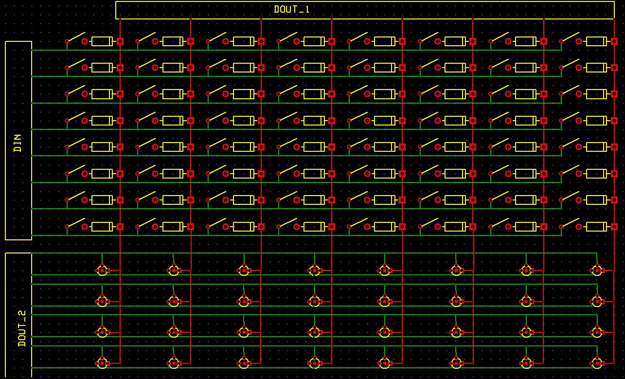
One 74HC595 is used as a current sink for 8 “columns” of LEDs and switches.
One 74HC595 is used as a current source for 8 “rows” of LEDs.
One 74HC165 is used to sample the state of 8 switches in one “column”.
The remaning 5 74HC165 are used to sample the encoder states. Four of these are close to the step encoders (to minimize traces), the fifth is on the far right and connects to the menu encoder. If you use encoders with switches, then the 16 step encoder switches (wired in parallel) and the menu encoder’s switch are connected to this 74HC165.
When putting switches in a matrix, you need to put a diode in series (in this case, cathodes are connected to the “column”), similarly the LEDs are connected with common cathodes. The diodes prevent false triggering if more than one switch is pressed at a time - without them, the current could be sinking switches on more than one column.
DIN/DOUT on the same PCB is good, but quite hard to layout, it takes a long time to find the best places to fit the ICs and then even more time optimizing the traces, thus you may start out with switches and LEDs at certain positions in the matrix and then swap them around. For example, the 16 step switches and 16 step LEDs are connected to the 8 matrix columns in a pattern - each column has two switches and two LEDs, but the left and right sides are in a different order. Similarly, the switches roughly below each pair of step switches are connected to the same column of the matrix, but thereafter the row connections are not always regular.
I’m not sure which resistors you say are missing - if you mean for the LEDs, then you only need one resistor per matrix row (i.e. connected to the 74HC595) but I’ve also used two sometimes, i.e. the 74HC595 connects to two resistors, one leading to some LEDs on the right side. If you mean missing resistors for the DIN, there are 6-pin 10K resistor networks next to each 74HC165.
BTW it is the same kind of switch/LED matrix I used on the MB-6582, with the exception that I do not use transistors for the columns, since the MB-6582 has two 74HC595 supplying a 16x8 LED matrix, the SEQ only has an 8x8 LED matrix. So you can see some kind of schematic in the wiki (http://www.midibox.org/dokuwiki/wilba_mb_6582 see “Control Surface Wiring”). Note the JDx connections are (essentially) 1:1 with DIN/DOUT D0..D8 pin outputs.
If this is your first time designing PCBs, perhaps it might be easier to do it like the MB-6582 control surface - don’t put the DIN/DOUT on the PCB, just do the matrix on the PCB and connect it to external DIN/DOUT modules. For an MB-SEQ (potentially 17" wide!) there will be plenty of room for DIN/DOUT modules in the case, so the matrix will just mean you need less DIN/DOUT modules.
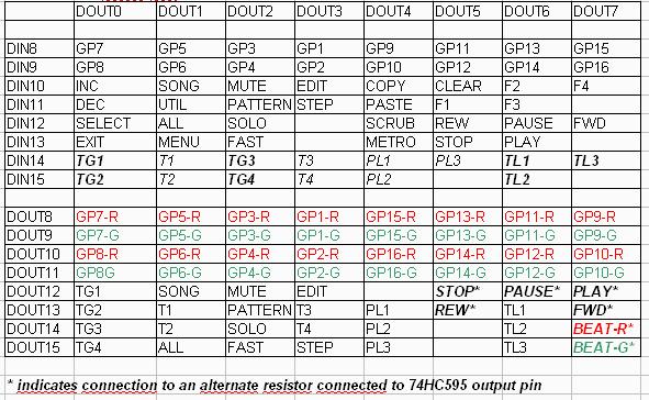
I’ve attached the matrix pin assignments, I assume this is correct, but it’s not really that important if it is not - you will need to define your own, but you could use this as a guide - i.e. see how I’ve arranged switches into columns to sort of match their horizontal location. If you match the GP LED assignments, that would be ideal, because then you can use the same code in MB-SEQ firmware.
=====
Attachment: [http://midibox.org/forums/index.php?app=core&module=attach§ion=attach&attach\_id=4925](< base_url >/index.php?app=core&module=attach§ion=attach&attach_id=4925)
Thanks Findbuddha, after what you told me I found this.
If I understand correctly (I am completely new to this subject) all encoders are wired to DOUT pin 0 and two DIN pins, and a bunch of buttons are connected to DIN Unit 2 and various DOUT pins via a diode(or is this diode set between the DIN and the button?)
Also, I don’t understand the use of Unit 8 (DOUT)yet, but I’ll have a go at that tomorrow.