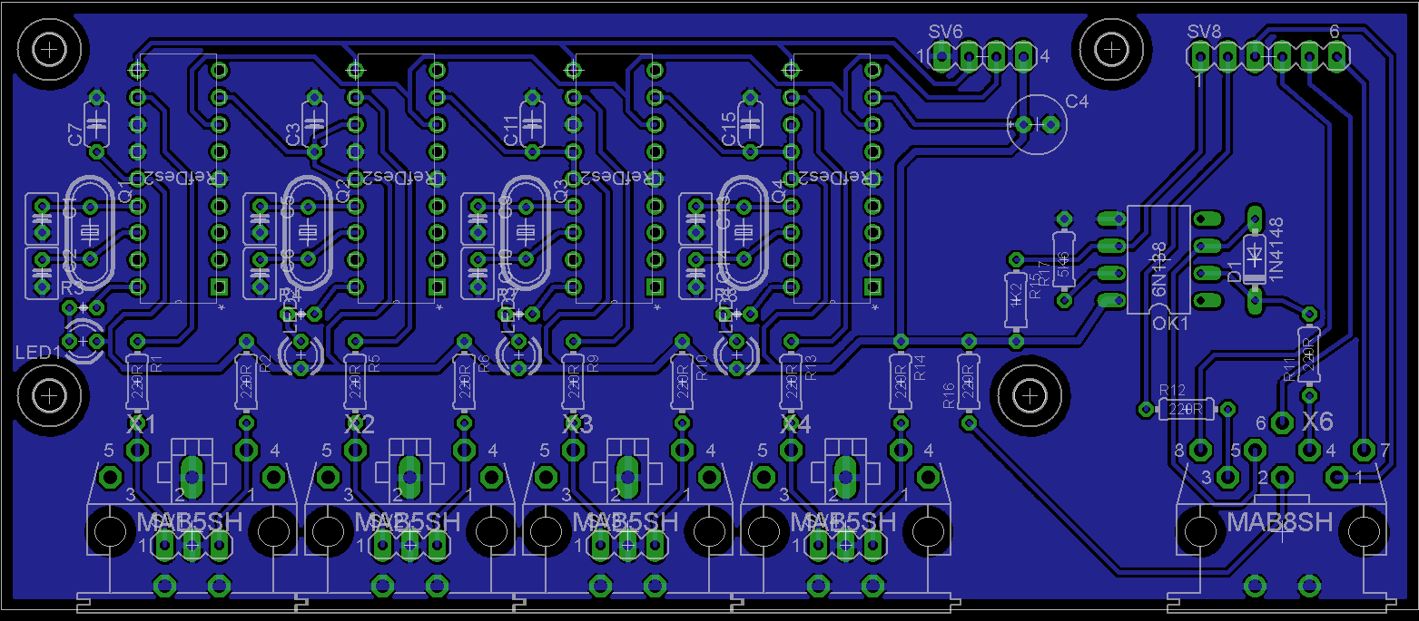
And here another idea: since the BLM will require an additional optocoupler and some resistors (a common TTL->MIDI IN and OUT circuit), these components could be added to the PCB as well (if still possible)
Best Regards, Thorsten.
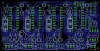
Done. I routed the pins for convenience with pin one and two being the midi in and out. I suppose one of those 8 pins should be gnd also..
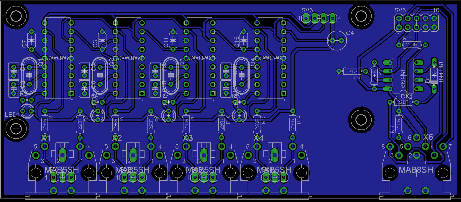
Could you please change SV8 to a 5x2-pin socket header? The layout should match with J11 of the MBHP_CORE_STM32 module (MIDI Link port). MI2 and MO2 can be used as spare pins.
Just to ensure a certain consistency.
The BLM socket and the surrounding circuit should use Vdd from this 5x2 pin socket, and not from somewhere else, so that it is possible to supply the BLM from a dedicated PSU if required.
Vss should be connected together with the ground of the IIC circuit
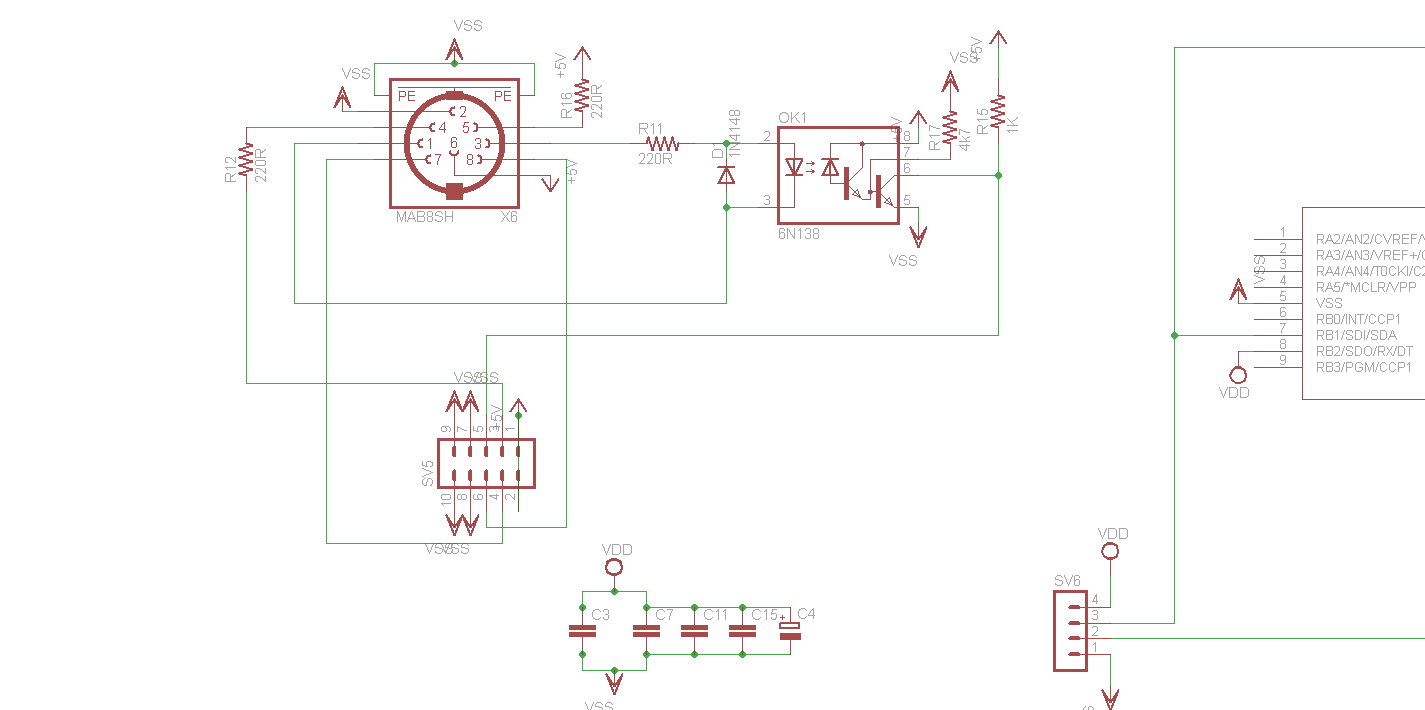
In order to make it more clear, I created a schematic for this circuit
Please note: the socket is drawn from the rear side, I’m not sure if this is also the case in your schematic (check with the layout view)
And btw.: a typical error is that people swap the MIDI IN/OUT pins when working with Eagle (ask Smash or Nils ;)) - please doublecheck the pinning with existing MBHP_* layouts.
(Update: I compared your layout with the MBHP_IIC_MIDI PCB, it seems to be correct)
And btw.: a typical error is that people swap the MIDI IN/OUT pins when working with Eagle (ask Smash or Nils ;)) - please doublecheck the pinning with existing MBHP_* layouts.
Hehe, who would do such a thing :whistle:
To clarify that: The reason isn’t/wasn’t Eagle, but the fact that in TK’s schem the MIDI sockets are viewed from behind, which apparently can confuse some simple minded people (like Smash and me obviously). If you wanna be cool, join the fun, be part of the group, swap the pins :yes:
I have the isolate on the small size (16) which may cause some problems for DIY etchers. I can do this no problem but I will release a revision with some jumpers and a 24 isolation as soon as this is done. My window is closing on access to the lab to make these so i want the basic layout done ASAP
As far as pins go, I just go by the numbers. The deltron sockets I use are all numbered..
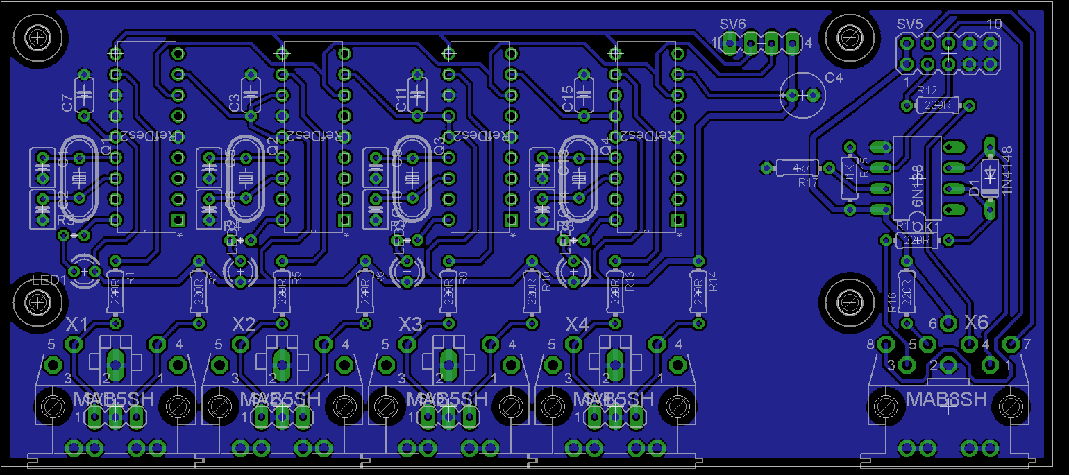
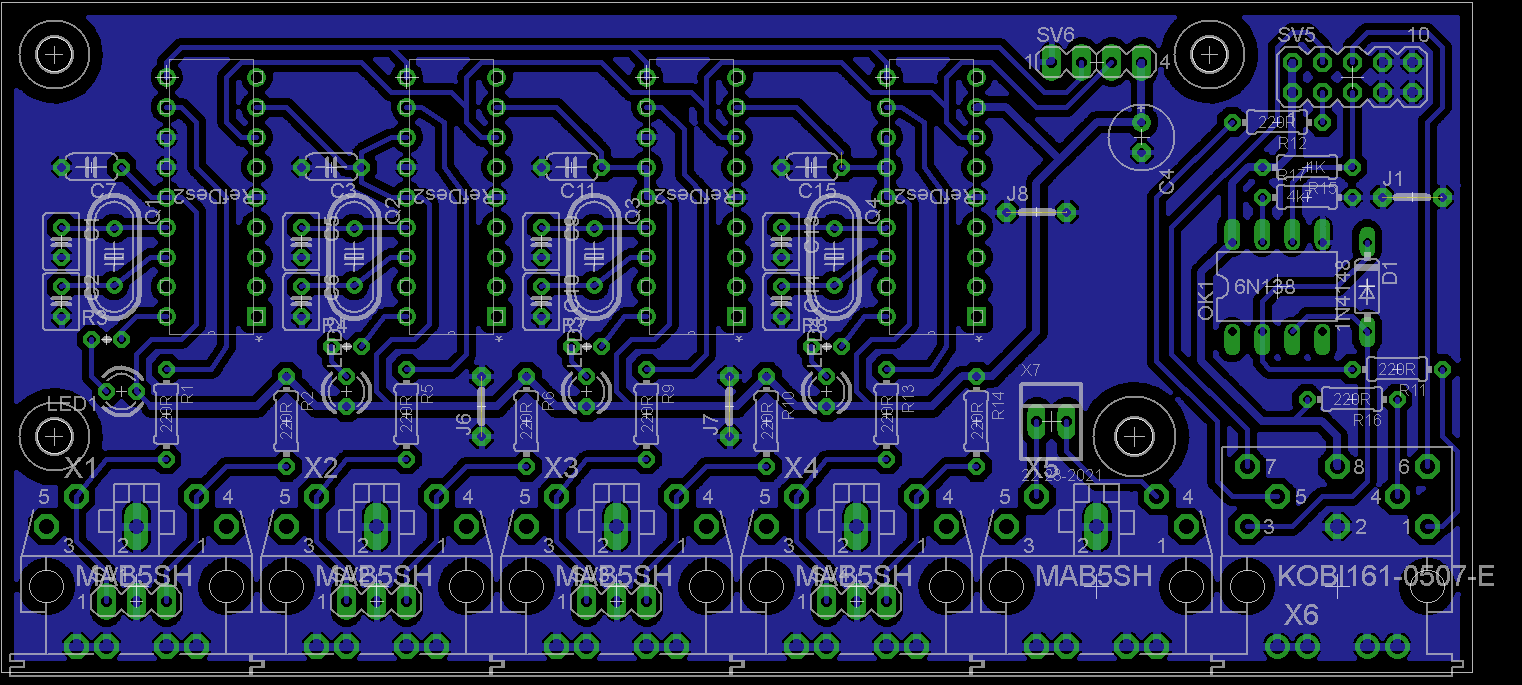
Up in this thread it was suggested to move the circuitry around the four ICs a little (1cm?) to the right, in order to save on board space on the left - is this still an option? To my eye, this should fit nicely. Also, you should then adjust the lower left mounting hole (the one near LED1) a little upwards, so that it is in line with the lower right one (you might want to do this regardless).
Up in this thread it was suggested to move the circuitry around the four ICs a little (1cm?) to the right, in order to save on board space on the left - is this still an option? To my eye, this should fit nicely. Also, you should then adjust the lower left mounting hole (the one near LED1) a little upwards, so that it is in line with the lower right one (you might want to do this regardless).
Done and done. The lower mounting holes have the same spacing relative to the connector side as the core32 for consistency(the lower right was off on the last rev), the top ones are different obviously since the board is not as deep.
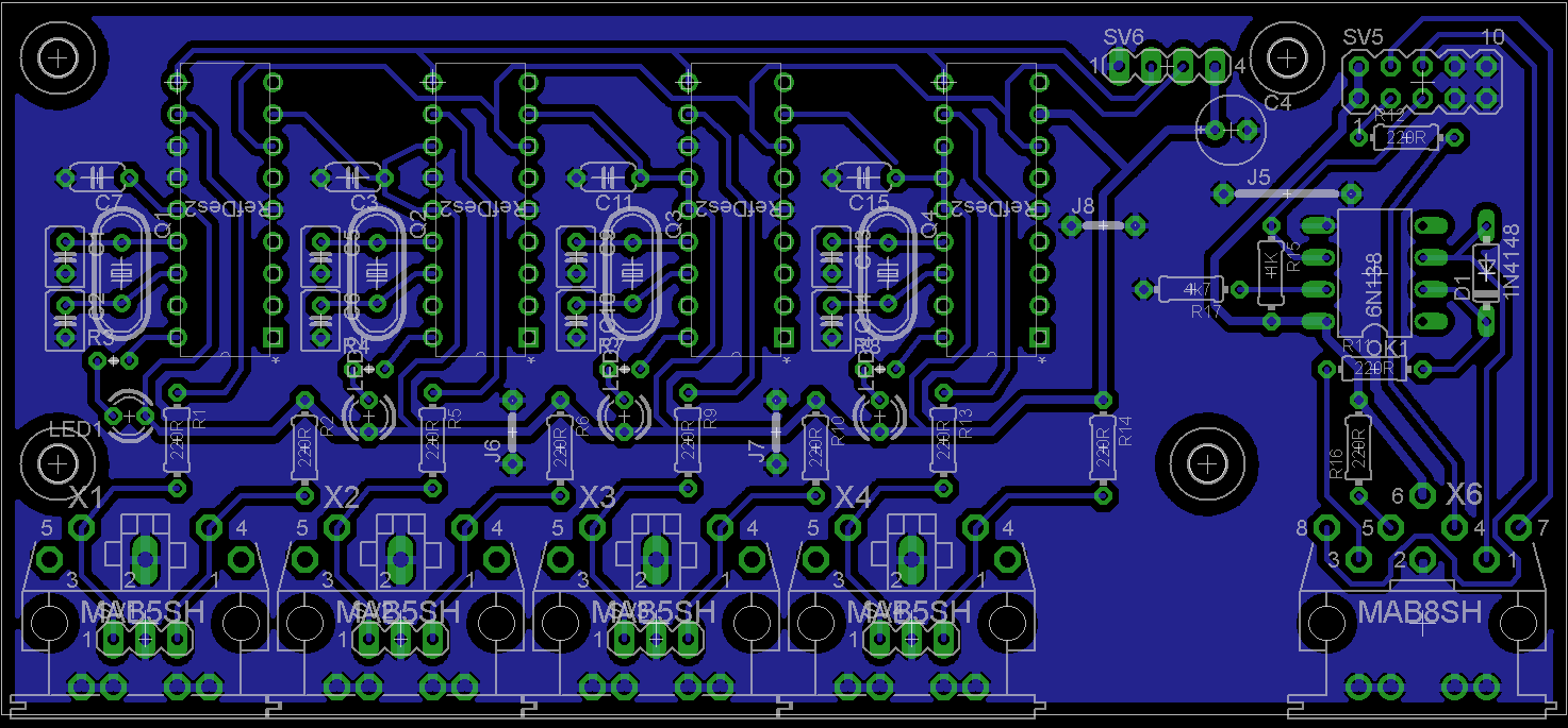
The second file is the 24 isolated version with jumpers for easier etching..
That mouser part is fine, I add added the extra pads for both the 5 and 8 pin connectors so ppl can use ones with either the 5mm or 10mm spaced pins in front. Like that pre-terminated 8 pin DIN cable though, might actually not be a bad idea just to terminate the wires that directly to the BLM instead of using the big DIN connector and save some space..
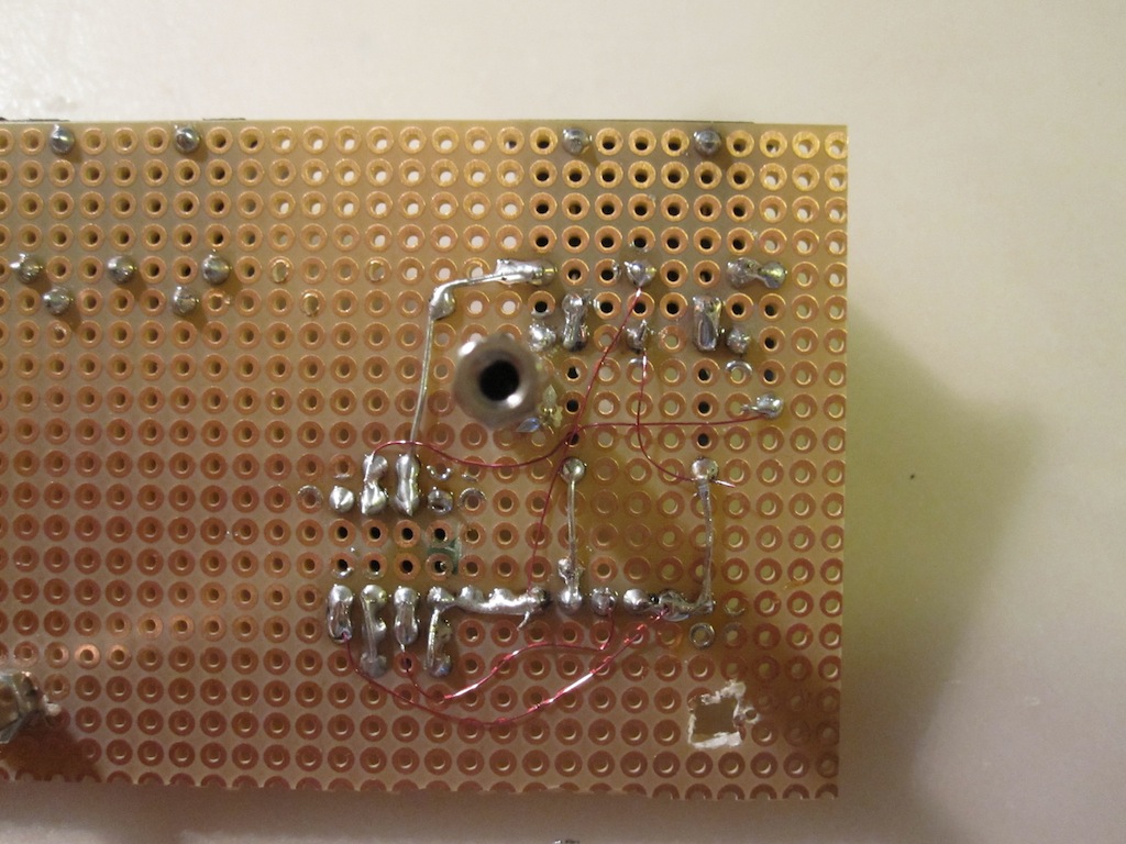
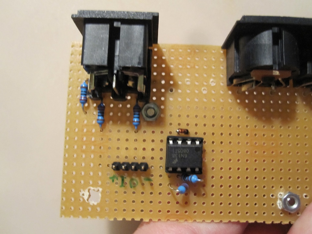
I’m just soldering my prototype BLM socket and noticed two things: some pins are swapped in your layout, and the footprint doesn’t match with the socket available at Reichelt.
Ok, kinda hard to trace those pics so here is the schem I used for mine, maybe it will be easier to spot the problem there.
As far as I can tell, pins 1 and 3 and 7 and 8 are swapped in your PCB layout but are shown the other way around in the schematic you posted. Can you confirm?
Also, regarding the footprint, either should work. I ran into that type connector with my last GM5, it is different since it does not have the click-in tabs but will fit the same footprint. I’ll make sure to leave more room though since the extra plastic around the pins needs more clearance
Ok, board revised for the Kobiconn connector available at mouser and reichelt. These are different from the hirshmann and CUI parts. Please see first post
It looks better now - the remaining risk is at your side!
Just a last proposal: you could prepare a “dummy DIN5 socket” between the 4th MIDI OUT and the BLM socket.
This would be helpful for the case that somebody doesn’t want to connect a BLM, but wants to add a third MIDI IN/OUT provided by the MBHP_CORE_STM32 module.
In this case he would need two DIN5 sockets.
The MIDI OUT could be soldered at BLM location, the MIDI IN at the “dummy” location.
You don’t need to add connections to the “dummy” port - if somebody wants to use it, he could connect MIDI IN pins via two cables.