This is exactly why I added a digital camera to my toolkit on the wiki last night. It might not get as much use as your soldering iron but it’s sure useful when troubleshooting gets tricky… And of course you can post images when you’re finished, to show off ![]()
the reason for this issue would be really interesting, because I also have no explanation, why another adapter should lead to higher voltages behind the 7805. There could be a short at the bottom of the PCB, therefore it would be helpful if you could post a photo of the front- and bottom side of your board (you can send me the pictures, I will put them on the server)
Best Regards, Thorsten.
Hi TK,
when testing prototype builds of my PSU I have also seen higher voltages behind 78xx regultators. The explanation I got from more knowlegeable (than me) people was that the 78xx needs a load before it will regulate properly. That may not be the case here since his core boards is acting as a load, but is it a big enough load without PIC running…?
Cheers, Alex.
the 78xx needs a load before it will regulate properly. That may not be the case here since his core boards is acting as a load, but is it a big enough load without PIC running…?
I’ve heard this too (can’t remember where)… You make a good point, but if there’s an LCD on there, I’d say that would be sufficient load.
Ah - thanks, now I also remember this effect. It should be documented at the MBHP pages
Best Regards, Thorsten.
ok guys igot a camera and now i can take the pictures so you all can confurm that i placed the parts right…?? right…
ok i now use a 9v 200 mA adapter for my core
TK will place the pictures i’m sending him after this…
About the other adapters i still dont think i understand … but if there’s a load on the adapter i current should go down…
Ok i have an other problem so ill keep it in this treat so someone new can see the varius problems i encounter and will encounter,
Ok mij SID module is ready but measerments are not ok because the whole ground in powerd, not very good mabey i made an intercinnection at the BC547 so i will sent the pidtures of that PCB to TK aswell…
Oh ja if i have an unstabelised adapter suppose to be 12V 1A, my multimeter reads about 15V can i use this for powering my SIDmodule?
Than i have one more question because i was thinking of using the PSU from my C64, can i measure the 9V AC comming out of the adapter? Couse i can find the 5V DC but not the 9V AC?
Well thanks guys, pictures will be placed by TK, thanks by the way!!!
Than i have one more question because i was thinking of using the PSU from my C64, can i measure the 9V AC comming out of the adapter? Couse i can find the 5V DC but not the 9V AC?
you have a digital multimeter? put it on AC ![]() (this symbol; ~)
(this symbol; ~)
or read this topic:
http://www.midibox.org/forum/index.php?topic=4850.0
and if you didn’t know allready; use this circuit; it has a real good signal to noise ratio
http://www.ucapps.de/mbhp/mbhp_4xsid_c64_psu_optimized.pdf
cheers
thanks for that illogik how stupid of me… i got it…
The files (>700k, very good picture quality) can now be downloaded here:
http://www.midibox.org/users/freaksomnia/PICT0002.JPG
http://www.midibox.org/users/freaksomnia/PICT0003.JPG
http://www.midibox.org/users/freaksomnia/PICT0005.JPG
http://www.midibox.org/users/freaksomnia/PICT0010.JPG
Here some smaller versions with remarks:
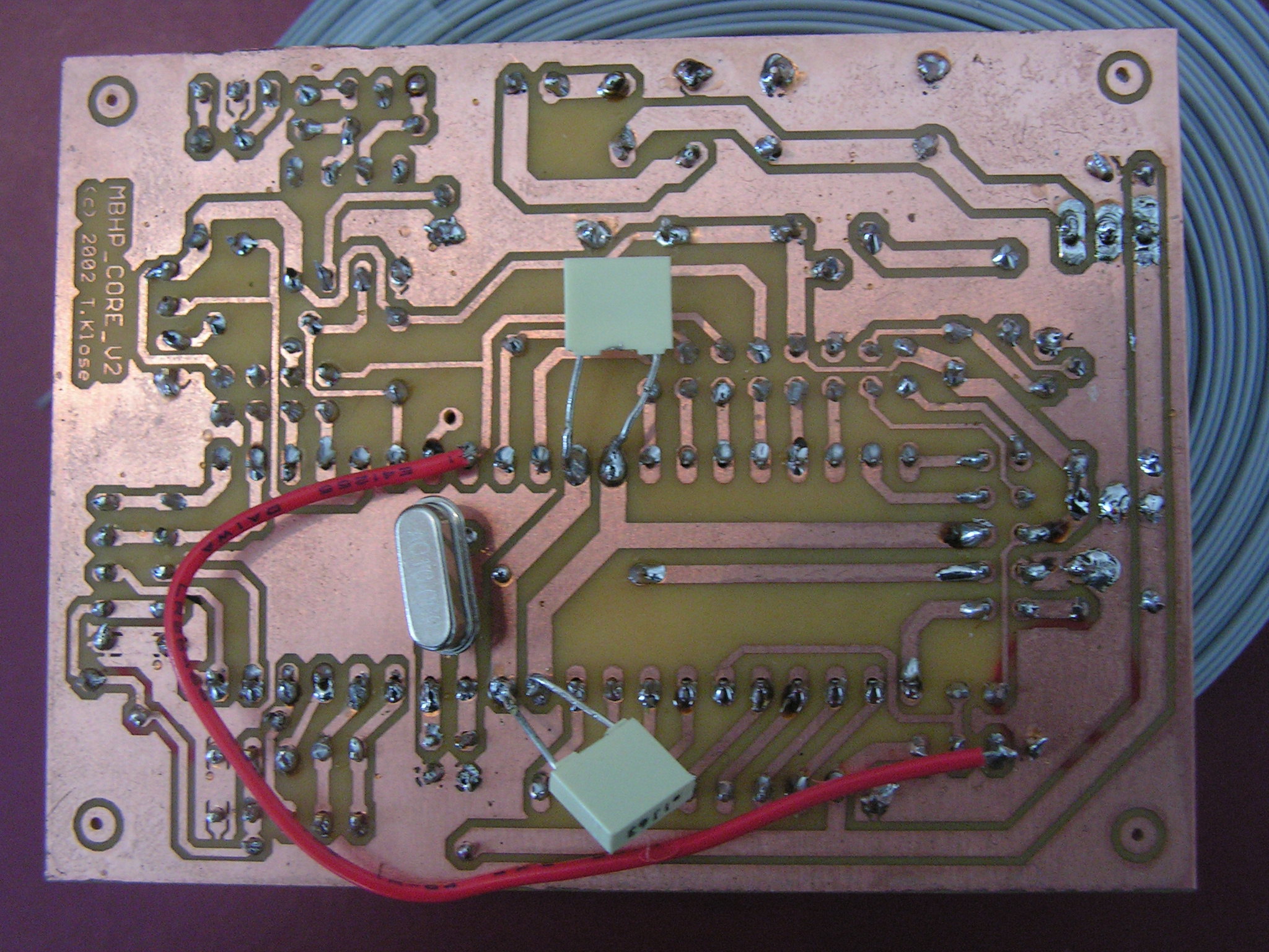
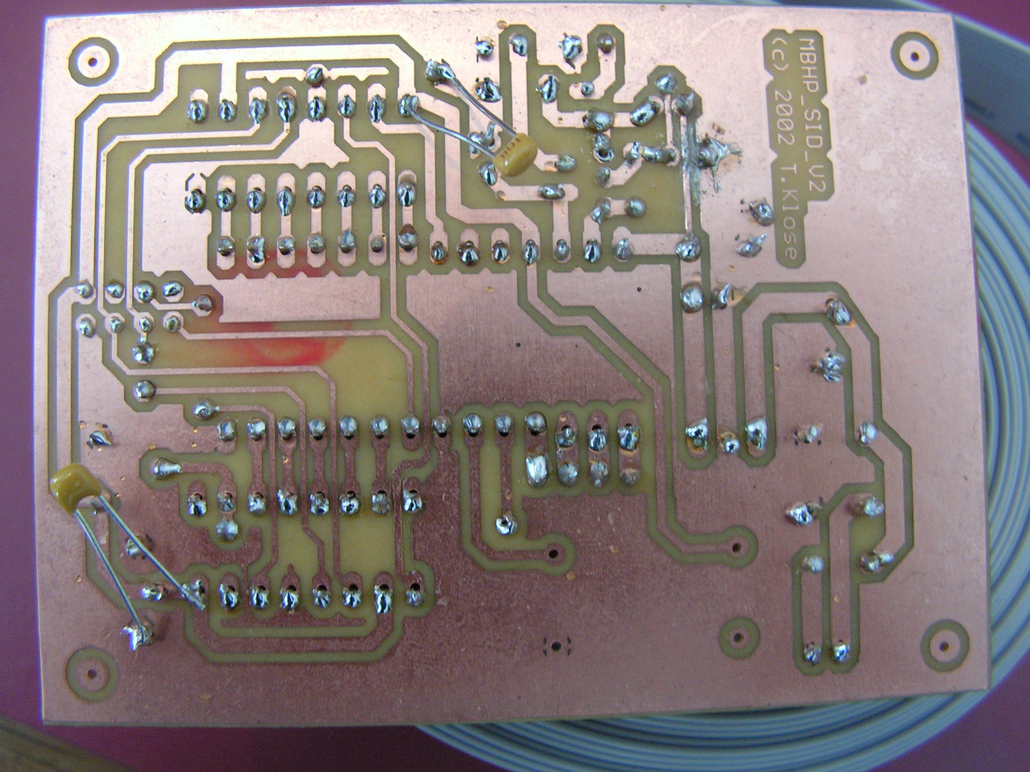
1: the core module has some bad solderings (loose connections), which could lead to failures. There are also missing solderings (e.g. 33pF cap below crystal). I would propose to solder each pad again, the soldering guide in the Wiki gives some useful tips
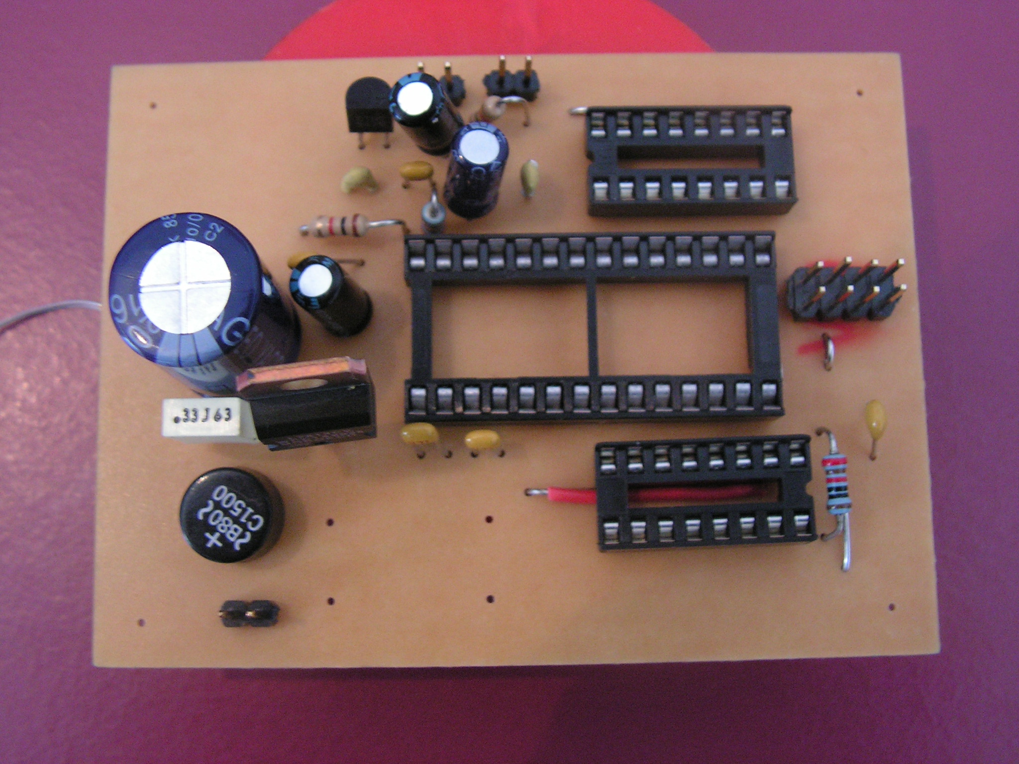
2: the legs of the caps should be cutted, otherwise they can cause a short circuit which can damage the PIC!
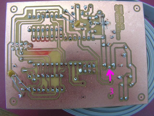
3: this seems to be a bad ground connection directly at the 78xx - it can lead to the wrong voltage. Here the same: just solder the pads again, it will help
And also cut the long cap legs, the danger for shorts is too high
Best Regards, Thorsten.
P.S.: I don’t want to bother you, but do you allow me to bring the two pictures into the wiki in order to explain other newbies, for what they have to take care about?

thanks for posting my pictures TK and thanks for the tips i will be correcting them a.s.p. ( i meen yesterday ) o yeah ofcourse you kan use the pictures… happy to help out with my bad soldering…
Ill let you know it it works.
Thanks Geert