there is a little error message, which the terminal outputs as soon as I start the midibox:
ok, I’ve to shorten the label name in the next release
And btw: Is there a chance so control the LEDs with the internal MIDI clock so it can act like an visual metronome?
MIDI clock event handling is still on the TODO list - so, yes, could be possible sooner or later.
//edit: just discovered another “bug”. When I set the rainbow on and run after that RGBLedClearAll not always all LEDs will go off. Sometimes (random) a few of them are still on in different colors (no rainbow effect). I’d need to use the command twice in this case to shut off all LEDs.
the rainbow effect is handled in the background task. It’s possible that it will be disabled from a higher prio task while new LED values are written, this results into the effect that you see. However, In the next release, LEDs should be cleared correctly.
The rainbow effect should still go on when you change between those two NGC files. But you an see that the speed differs. Is this meant to be like this?
yes, it’s plausible: timings are not ensured when functions (like the rainbow effect) are called from the background task. The AINSER module will cause some additional CPU load and this will slow down the rainbow effect.
Not critical from my point of view (assuming that we are talking about a testing feature)
Well… it would be possible. But you would need to send A LOT of MIDI messages on patch change. I had no idea yet how to get around this…
And finally: The distance between each LED is not the same as the keys… so not every key has it’s LED. I have 71 LEDs on the lower board and not 88 Anyway… it’s already such a nice feature… I LOVE IT!!
According to adafruit, there are at least two LEDs with different names that use the same controller (or an equivalent). I think they should work; you should choose the 5mm LED as 8mm is too large.
At some point I will sell the PCBs to suit (don’t buy Sparkfun PCBs unless you want to use common RGB LEDs), price should be about 8 EUR.
If you read through TK.'s code example on svnmios32, he states that driving the LEDs takes up quite a bit of memory but not too much CPU overhead. There is a limit in the chain length in order to guarantee data transmission. I’m pretty sure that the controllers hold the colour value and new data is only required for updates. The advantage of shift registers is the parallel data transmission which allows for a simple serial stream to rapidly clock multiple lines. Disadvantages are the complicated PCB and software matrices, but it does work (BLM 16*16+X).
My words were confusing, i now understand better the principle of serial chain color driving through the code.
So to drive for example 64 LEDs you just need a chain linking them to CORE32 J4B.SC! Wonderful =)
That’s pretty nice for PCB routing ^^
I talked about matrixes because that’s the way i am going to dispose my LEDs physically.
And the current most efficient way to drive an amount of monochrome LEDs is matrix shift register design.
At the beginning thought there would have kind of differents buses to handle or similar things to shift register design.
And that is very good about default params i was planning to use 64 RGBs APA 106 LEDs =D
Thanks for your answer Thorsten =)
Best Regards,
Jérôme
Here’s a souped up version (intended for Programma):
All registers on board.
45 degree styles
Room for OLEDs
Individual touch sensors, wired to encoder bodies at the moment.
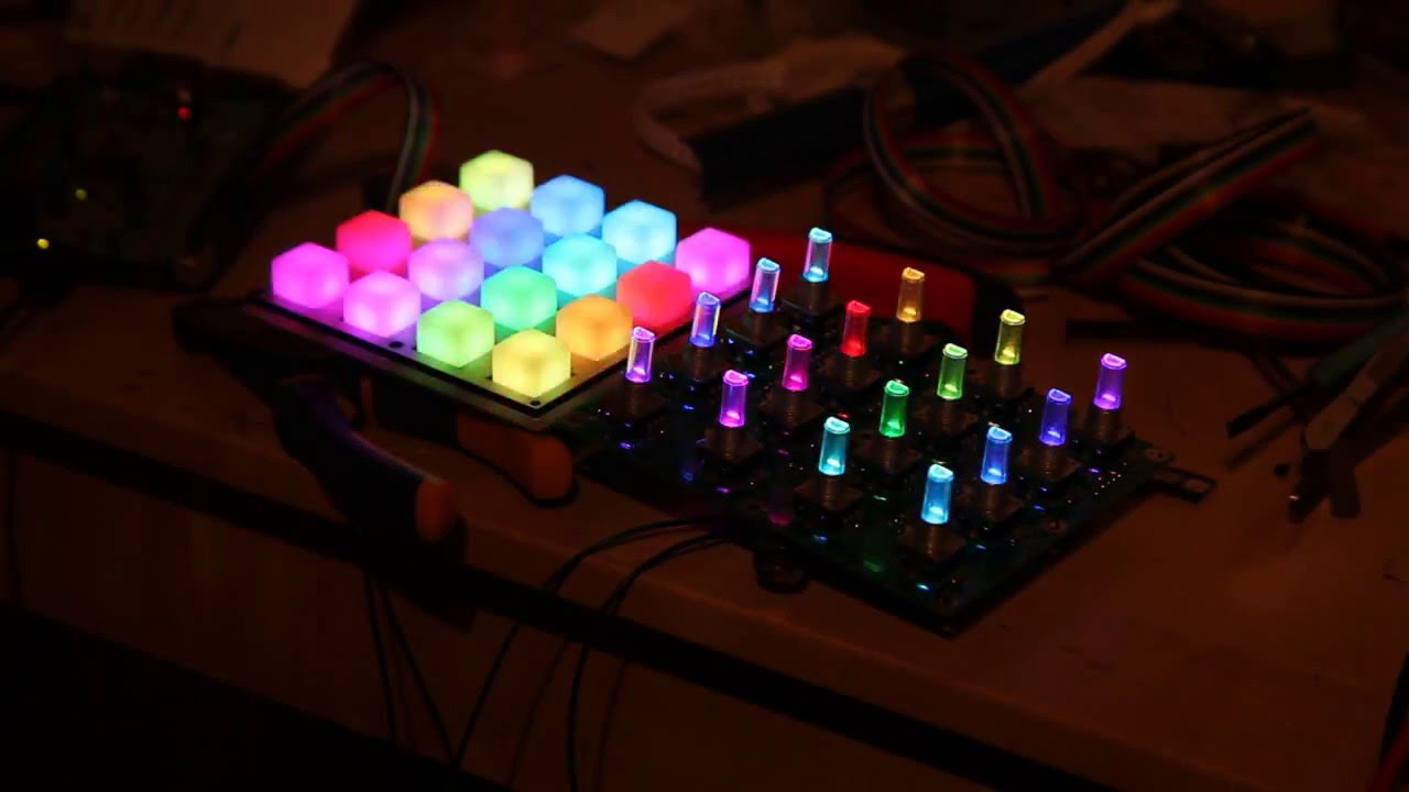
A bit hard to capture the LEDs, but I hope you get the general idea. The touch sensors are set to activate the LEDs and they can be “dimmed” using a MIOS CC value. It’s very preliminary for the moment, but eventually the idea is to use the touch sensors to turn on the acceleration function of encoders. That needs a bit of thought though.
Today I did some experiments with RGB LEDs, e.g. to evaluate Andy’s idea to use a single RGB LED as replacement for LED rings around encoders:
Outcome:
a LED matrix configuration doesn’t give us enough brightness levels. E.g. I tried a 4x8 matrix which allows 8 brightness levels for each color, but it turned out that dim values above 4 (50%) don’t make a big difference anymore, accordingly the actual resolution was only 2 bit (4 brightness levels)
therefore I connected the R/G/B LEDs directly to DOUT pins, which gives us up to 16 dim levels and higher brightness (since no multiplexing takes place). Results where much better!
Conclusion: if LED rings should be replaced by RGB LEDs, we need 3 dedicated DOUT pins per LED, makes 48 pins for 16 RGB LEDs = 6 DOUT SRs
Line drivers are not required, since the DOUT SRs are strong enough to drive the LEDs.
Best Regards, Thorsten.
Seeing how it looks like we’re going back to a shift register-driven RGB BLM in 8*4 config, I’m curious if you connected any current source/sink in this setup (if you remember).
Does someone know if it’s possible to use the WS2812 as matrix? I’m afraid that there is no parameter called EVENT_RGBLED_MATRIX. So there might be a workaround that I don’t know?
I’m looking for a replacement for the classic encoder led rings and those WS2812 seem to be a great alternative.