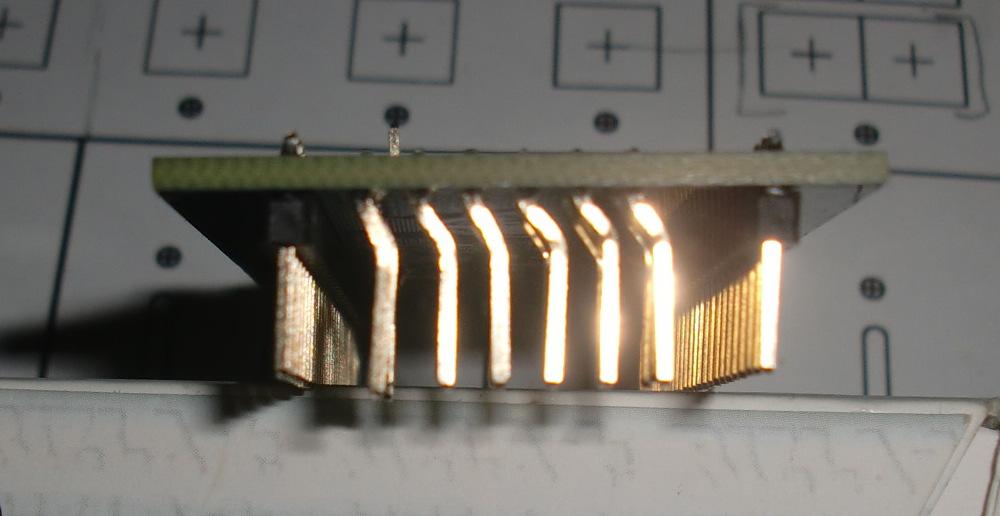
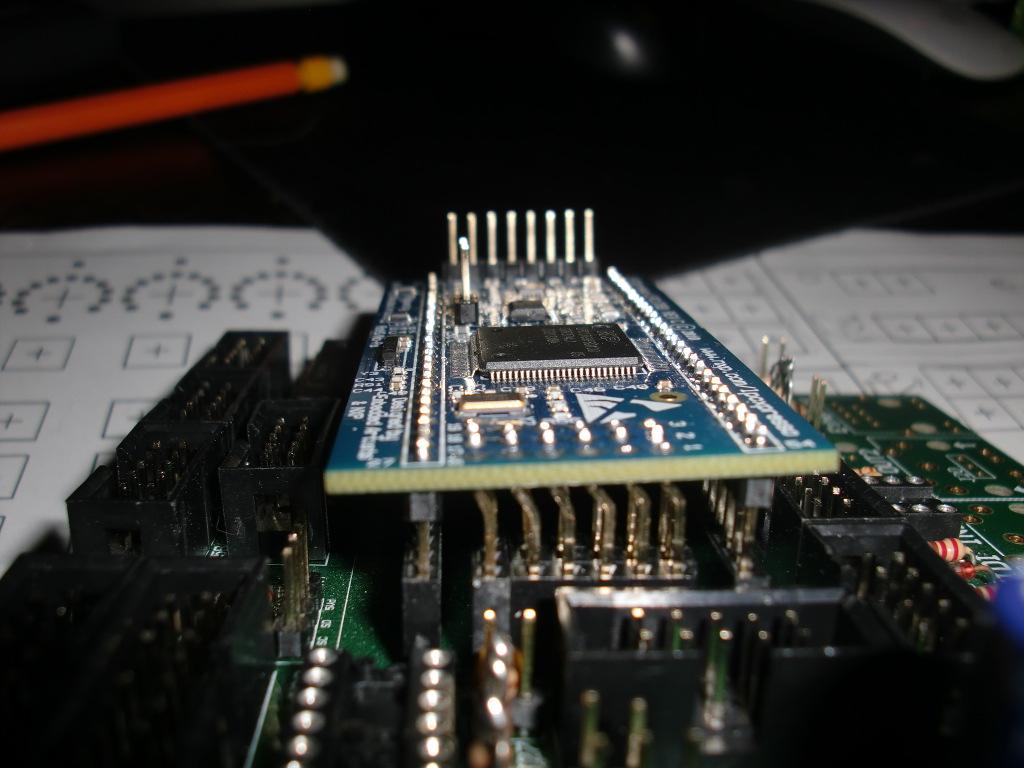
The row of holes has not moved that far on the rev c board.
Well that’s strange because from the picture that jab uploaded in the first post of this thread, it looks like we have an offset of exactly 1,27mm for pins 1-19:
Looking at this, I think you are not actually talking about these pins, but that you soldered the two rows of headers onto LPC and core board separately and tried to stack them afterwards. That is not recommended practice anyways. So it seems like you are referring to something different than what this thread was originally about?
No, I’m talking about the same thing, but I had assumed that the row of pins along the top of the LPC were the pins that were moved, not pins 1-19. But obviously looking at the picture, it’s pins 1-19 that moved. It’s hard to tell looking at my board, since it’s all soldered together at this point.
Regardless, having just assembled the board with the rev c LPC, I think that anyone trying to assemble with a rev c should try putting the pieces together before soldering, and then soldering them in place. They won’t be able to fit the header pins all the way into the holes, but they will fit and the connections will work without a bunch of rewiring. It would be easier to fit them that way than it was trying to fit them after they were soldered into the LPC.
Certainly, there’s no harm in trying that anyway. If they don’t fit, then you can try another approach, since you won’t have soldered anything.
You’re welcome to disagree, of course, if you like, and your wire-with-cut-resistor-legs method would also work.
Regardless, having just assembled the board with the rev c LPC, I think that anyone trying to assemble with a rev c should try putting the pieces together before soldering, and then soldering them in place.
Yes, that is the recommended method anyways, even for the older rev B.
You’re welcome to disagree, of course, if you like, and your wire-with-cut-resistor-legs method would also work.
Yes, that is the recommended method anyways, even for the older rev B.
Yeah, I should have tried fitting them before soldering, but after building a bunch of projects like this it’s easy to get lazy and just assume things will fit. Hopefully other people will notice this thread before putting their Core boards together and they won’t make the same mistake.
In other news, the v4l is a great little sequencer. I’m looking forward to getting the V4 frontpanel PCB whenever they’re back in stock and putting that together…
Hey guys, since there’s been more discussion about this (and maybe for my own closure) I thought I’d show my solution to this, it’s similar to what’s been previously mentioned:
I don’t plan on using this hardware with anything else, but I still wanted to make the parts removable. I tried to find a method to put a bend in the male headers, but I couldn’t make consistent bends, so I scrapped that idea. Then I noticed that the pins on the female headers are thinner, and could be formed pretty easily - just pressed the leads at a 30ish degree angle against my workbench, and decided to see if I could make this work
So I soldered in male headers to the core module (a few pins only to start), then fit the female headers to the LPC and tried to line everything up - which took a little time but was possible.. There’s a gap between the header and the pcb, but in my case the leads were long enough that I still had enough to solder to. I soldered a few pins on the LPC, and then tried removing the LPC with the headers attached - it’s a tight fit, but possible. So then I plugged it back in and soldered the rest.
Continuity checked out ok for all pins. I haven’t tested all the functionality of my core module yet, but so far I haven’t found any connection issues. LCD 1/2, DIN/DOUT, and SD card all are working well.
Anyways, I’m sure my EE professors would cringe if they saw this, but I’m an ME, so I’m going to use that as my excuse Not the cleanest solution, but so far it’s working out, and while I don’t make a point of removing the LPC, it’s nice to have the option available. Hope this is some help for folks that find themselves with a rev C LPC.
As this thread is about the LPCXpresso board from _ Embedded Artists _, does someone know if they changed the layout for the boards which are produced by _ NXP _ himself (OM13000,598)?
As this thread is about the LPCXpresso board from _ Embedded Artists _, does someone know if they changed the layout for the boards which are produced by _ NXP _ himself (OM13000,598)?
Would go the STM32F4 route, but I already purchased all the boards from SmashTV…
Not sure if there is a difference between boards produced by EA/NXP (my understanding that it was something of a joint venture and there was only one manufacturer, but perhaps not?). For what it’s worth, I looked back to my thread on the NXP forum, and EA did eventually document the change: link
I had the LPC17 core PCB for a long time, but ordered the LPC1769 only last week.
Yesterday morning when I wanted to solder the header I was surprised when I noticed (before soldering) that they don’t match the one on the PCB…
After reading that post, I decided to solder them, remove the black plastic holder, and bend the pin to match the already soldered(about 1 year ago…) female connector on the PCB (The header on LPC1769 were soldered not “fully inserted”, so I have enough room on each pin to bend them 2 times).
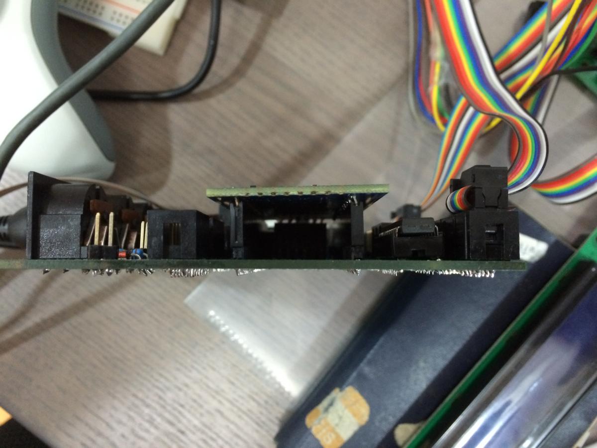
 Not the cleanest solution, but so far it’s working out, and while I don’t make a point of removing the LPC, it’s nice to have the option available. Hope this is some help for folks that find themselves with a rev C LPC.