Extended front panel design - what to do with two extra buttons?

Thanks Peter!


I would really recommend to test it out on two DOUTx4 boards and put the LED digits and the LED matrices on a breadboard before ordering a PCB.

As murphy says, likely some wires are wrong, I experimented on breadboard until everything worked and the LED digits displayed “sane” numbers… then soldered it up, unfortunately not taking notes, how the connections were done…


That I have obviously done already - a few months have passed, so there was time for this. Also, I suspect that the pinout for the LED matrixes is not the same with every brand, and even the data sheet I got for mine was wrong.


… the push-to-accelerate bus is simply an additional (encoder-)switch, that is connected between GND and the FAST2 DIN pin of the standard MBSEQV4, you can wire up many of these switches and accelerate the SEQ by pressing any of them, but you would probably need only one, for the BPM encoder.


Great, so the jumper/connector is sitting on the right end of the switch.


… the pinning of especially the digit segments cannot be changed in software (as of yet) - it would be nice, to get the digit segment wiring “right” in hardware, so that it is compatible with other implementers of the SEQ V4 BPM displays, e.g. the 808 SEQ project, that uses BPM digits as well… that´s why, it needs to be tested on breadboard, first.


For the LED digits I am simply following the official schematics.


Note, that the track-position-display code does not support “four” matrices (red1, green1, red2, green2) as of yet. I´d therefore recommend, that you test the four matrix wirings with the existing code:

just configure different matrix anode out shift registers and cathode shift registers, and see if all hardware wiring works as expected, i.e. the right LEDs light up for every of the four combinations!


That has been done - obviously I am not going to shell out money for a PCB that is based on schematics that have not been breadboarded. I was rather looking for comments on changes that might make your life as a programmer easier. Apparently there are no such proposals, so I’ll just go ahead :smile: .


Best, ilmenator

Hi ilmenator!


Great, am really looking forward to it - the PCB will be attached to my “mobile” SEQ, a bit of bling is necessary all the time :smile:. Also, I guess other MBSEQ users would love to have one, but let´s get it up and working first :smile:


For the LED digits I am simply following the official schematics.


That´s the only suggestion I have, please test that LED segment/digit wiring as well - i am not 100% sure, the official schematics fit with the currently active code, which would not be so bad, if there had not been people out there also deducing the wiring from scratch (also testing on breadboard - the most notable user is the MB9090 project), so we should make sure, that we all share the same hardware wiring, which helps to reduce complexity in software.


Best of luck and thanks for your efforts!

Peter

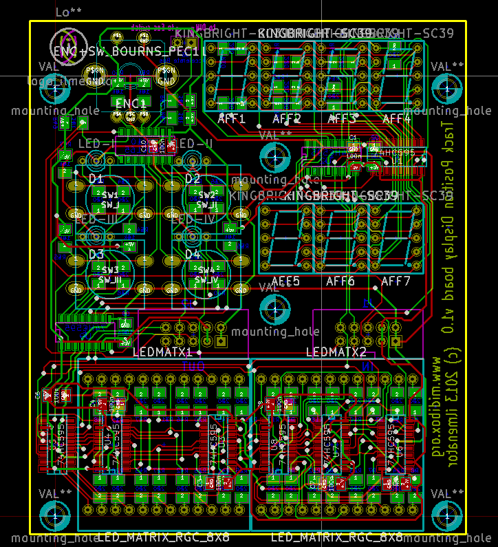
After a weekend of trace tetris I have a board design. It’s a bit crowded there and not for the shy :pirate: . Harrrrr. Now I wonder if I need to test the official BPM display schematic like Hawkeye suggests or not? TK?


Your extension looks great. If you design your own PCB’s for the extension I would be very interested in a set of them :slight_smile:


What kind of buttons will you use for the 4 x 16 matrix ?

After a weekend of trace tetris I have a board design. It’s a bit crowded there and not for the shy :pirate: . Harrrrr. Now I wonder if I need to test the official BPM display schematic like Hawkeye suggests or not? TK?

Looking forward to see the design finalized!


Your extension looks great. If you design your own PCB’s for the extension I would be very interested in a set of them :slight_smile:

So do I, though I probably will use some spare LCDs from my shelf-supplies so the pinout cannot be expected to fit, I hope I’ll be able to solve it using wires.


What kind of buttons will you use for the 4 x 16 matrix ?


Sorry for answering for ilmenator but since i have one of the boards as well these are Marquardt 6425 buttons (with no LED) with the 16mm cap.

Now I wonder if I need to test the official BPM display schematic


Please test the LED digit schems before ordering any boards, you may hit me with an arctic snowball, if I am wrong ;-), but if I remember things right, the segment order was messed up when testing the official schems - that´s why I got garbled digits on my 1-digit bpm board at first.

It only worked after wildly rearranging spaghetti on the breadboard  ;-).

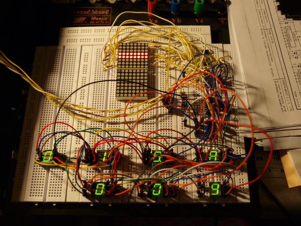
Ah yes, and it is highly unlikely, that the problem was caused by the few cables in the blurred part of the picture ;-).


Many greets,

Peter

ok, I have received the Reichelt order today and will take the stuff with me when returning home tomorrow. I’ll do testing next week, so the time frame for receiving the boards would be 4 weeks from then. No arctic snowballs :-).

Cool! Maybe really my DOUT pins were wrong at the connection point, but better be safe than sorry ;-).


Another thing, I hope the luminance of all LEDs will be high enough for you - I ended up direct driving them all (no resistors) - which is not a nice design choice, but even with 50 ohms resistors, the brightness was a bit low otherwise. This was probably because of the quite short duty cycle, as the number of digits was expanded from 3 (classic BPM) to 7 (4x BPM, 3x Step Display). Maybe a kind of LED driver  similar to the one on the new LED-Ring boards would be nice, but this is already outside of my knowledge area (which is software), so I cannot give further advice ;-).


Many greets,

Peter

I am not sure the ULN drivers make any difference at all. There was some discussion over in the LED ring board thread, but I don’t think there were any definitive conclusions on whether they would help the LEDs brightness or not. As the limiting factor seems to be the duty cylce and not the driving current, I doubt that the ULNs would make a difference here. Also, as you can see from the image above, this board is really short of remaining real estate for placing even a single ULN.


I’ll check how the Kingbrights behave, though, and think about alternatives if necessary.


Best, ilmenator

So I checked the official BPM schematic for pinning and brightness, and the results are very promising. BPM and STEP segments are connected to the same shift register, and the brightness is totally acceptable using 220Ohm resistors and 7 Kingbright SC39-11 type 7-segment displays all at once, with no additional drivers. Brightness is obviously increased somewhat by using 100Ohm resistors instead, I did not test lower values than that.


If you look closely you might see that when taking the picture I was using 220Ohm resistors for 4 segments (including the dot) and 100Ohm for the other 4 segments. However, that is a (visually) small difference.


I’ll place my PCB order soon, I’ll pass on one of the boards to Hawkeye for software mods of the TPD matrix.


Great news, looking very fine so far! Sorry for the additional workload, but better to test first! :slight_smile:

Many greets!

Peter


PS: When its done, your SEQ will be onehelluva SEQ :wink:

Sorry for the additional workload, but better to test first! :slight_smile:


You actually had me worried for around half an hour until I discovered that the upper and the lower part of my breadboard’s vertical power rails are not internally connected, leaving the last shift register in the chain floating, which resulted into VERY strange effects… :shocked:

until I discovered that the upper and the lower part of my breadboard’s vertical power rails are not internally connected


:slight_smile: Been there myself!

Board has been ordered, delivery in about 3-4 weeks to my place.


Board has been ordered, delivery in about 3-4 weeks to my place.


Looks nice, congratulations! Did you order 1-2 prototypes only for initial testing an then consider ordering larger amounts (if at all)? The obvious reason why I ask is that I’d love to test/usr one, too :slight_smile:

Cheers,

freddy

Nice board, nice PCB color, nice SMD shift registers and resistors - can´t wait :slight_smile:


Many greets,

Peter

Looks nice, congratulations! Did you order 1-2 prototypes only for initial testing an then consider ordering larger amounts (if at all)? The obvious reason why I ask is that I’d love to test/usr one, too :slight_smile:


The order placed was for 3 prototypes only and comparatively expensive looking back at the 16x4 BLM PCB. However, there are some tracks on this board that are running between the smd pads for the shift registers - I did not want to take any risk with respect to board quality.


Let’s discuss larger quantities once the design has been confirmed to work :smile:. At least the size of this one is much more shipping friendly than the 16x4 BLM board.

The order placed was for 3 prototypes only and comparatively expensive looking back at the 16x4 BLM PCB. However, there are some tracks on this board that are running between the smd pads for the shift registers - I did not want to take any risk with respect to board quality.


Let’s discuss larger quantities once the design has been confirmed to work :smile:. At least the size of this one is much more shipping friendly than the 16x4 BLM board.


Ilmenator,

understood and, of course, agreed. Looking forward for the bulk (if it happens), I’ll wait with ordering the front panel - it fits so nicely next to your 16x4 BLM :slight_smile:

Cheers,

freddy

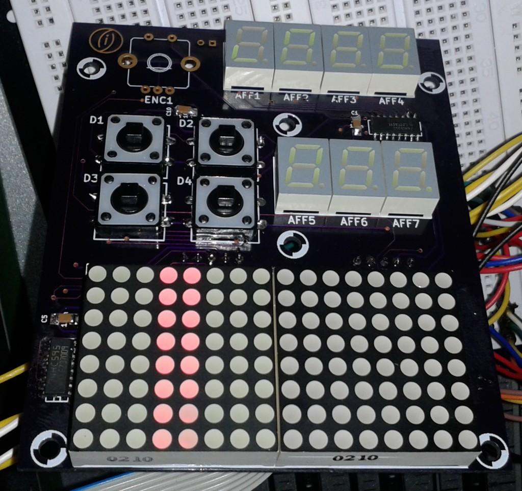
Boards have arrived (pretty fast this time!), and of course I managed to mess up the segment order on the 7-segment displays…
 

… but if I remember things right, the segment order was messed up when testing the official schems - that´s why I got garbled digits on my 1-digit bpm board at first.


So there will be some wire wrapping tonight to get it right again. The strange thing is that it WAS working okay on my breadboard, but apparently I got it wrong when transferring that to PCB - probably because I got confused by the DOUT module’s pin numbering. I think that is one of the most effective pitfalls that MIDIbox has to offer :rofl: .


The other interesting thing is that in the 8x8 duo LED matrix, the “other” color is always on, presumably because the corresponding shift register is not properly set, as it is not defined in the config file (yet).


Oh, and sorry for s****y phone camera picture. In real life the colors / brightness are totally okay :smile: .

That looks great, good work !


Freddy: Wait until the design is finished before you order your parts. Otherwise you have to sell your unwanted parts again :smile: