Wilba’s got mine, but that’s something I’ll have to nag him about ;)
Where’s my eucalyptus stick when I need it?
Oh there it is
*whack*
Wilba’s got mine, but that’s something I’ll have to nag him about ;)
Where’s my eucalyptus stick when I need it?
Oh there it is
*whack*
I bitter git on wuth ut eh bro?
Beer sometimes helps
There you go
Retrieved mine from the customs few days earlier.
Thank you very much! 
All,
Nsunier and I were discussing offline the background brightness of the Optrex LCDs. The LCD I’m using on my MB-FM has an only slightly brighter background than the yellow-on-black CrystalFontz LCD I have on my MB-6582 (which I’m very happy with), so I was fairly happy with background brightness on the Optrex display using a regular core module.
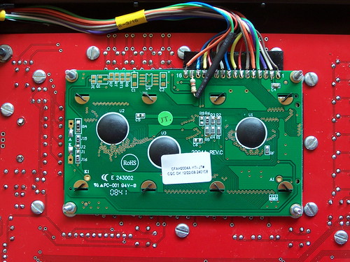
However, Nsunier was wanting a dimmer background so for fun I did some hacking about today on my core board (R4d from SmashTV). The LCD backlight brightness is controlled by the resistance through the 10k trimpot P1 and 1k resistor R4. These affect how much current the backlight gets through transistor T1. So with the default parts you basically can vary from 1k to 11k in resistance. (Those with more electronics knowledge than me, feel free to jump in with corrections!)
After experimenting with a 500k trimpot I found my preferred brightness around 35k - 40k total resistance with the LCD I have. I had to adjust contrast trimpot P2 slightly but I got a fairly dark background with minimal dimming of the characters. Greater resistances seemed to dim the characters at about the same rate as the background so no further gains in display quality were forthcoming.
I plan on changing out P1 on my core board with a 50k trimpot (Mouser part number 531-PT6KV-50K). I’ll probably leave R4 as-is (the bulk of the resistance will be coming from the trimpot), though other values could be used of course. A 100k trimpot could also be used, especially if you want an even darker background.
Overall I think you will be fine with the “default” 10K trimpot as specified in the design (and supplied by SmashTV for example), but for those wanting near perfection, I recommend using a 50K trimpot for P1.
Happy November!
Regards,
Chris
for the record, if you already soldered the lcd pots and don’t want to mess with the pcb, you can add a resistor between led+ wire/ pin 15 on the lcd, lcd on my mb6582 worked fine with an 8k res(low mA led lcd)
you could try with a 50k potentiometer to get a proper value, then just replace the pot with a resistor
I’ve got one of these:
Very handy!
I’ve got one of these:
Very handy!
Hey, that’s pretty handy. I just used a dual-gang 500k linear pot. One, er, “gang” was the resistance in the circuit via minigrabber clips and the other gang was hooked up to my multimeter. But having resistance pre-printed is rather nice…
for the record, if you already soldered the lcd pots and don’t want to mess with the pcb, you can add a resistor between led+ wire/ pin 15 on the lcd, lcd on my mb6582 worked fine with an 8k res(low mA led lcd)
you could try with a 50k potentiometer to get a proper value, then just replace the pot with a resistor
Doesn’t this approach (soldering between LED+ and the wire) drop the backlight voltage? By changing resistance at P1 or R4 (per my recommendation) you are changing how much current flows through T1. I need to break out my electronics book to sort this out for sure (I’m sure there’s an Ohm’s law problem in here somewhere!) but I guess if this approach works also it is nice to have options. Might have to give this a try just to see if I can get even better results out of the display…thanks for the input!
Doesn’t this approach (soldering between LED+ and the wire) drop the backlight voltage? By changing resistance at P1 or R4 (per my recommendation) you are changing how much current flows through T1. I need to break out my electronics book to sort this out for sure (I’m sure there’s an Ohm’s law problem in here somewhere!) but I guess if this approach works also it is nice to have options. Might have to give this a try just to see if I can get even better results out of the display…thanks for the input!
ah, probably you are right(electronics newbie here), I just measured the backlight voltage after the resistor to be sure it was between this particular lcd specs… after burning a $30 lcd because I didn’t read the datasheet and connected that lcd without any mods
of course I got the intended effect of a darker backlight after all.
let us know what you find out on your tests please 
Doesn’t this approach (soldering between LED+ and the wire) drop the backlight voltage? By changing resistance at P1 or R4 (per my recommendation) you are changing how much current flows through T1. I need to break out my electronics book to sort this out for sure (I’m sure there’s an Ohm’s law problem in here somewhere!) but I guess if this approach works also it is nice to have options. Might have to give this a try just to see if I can get even better results out of the display…thanks for the input!
All resistors in the signal path add up since thay are connected in series. They will all have the effect of limeting the current flowing throw the cirquit. If the voltage at the LCD inlet is affected depends on what more resitance there is in the other parts of the signal path. It has the same effect to 1) change R4, 2) change the trimpot and 3) add additional resistors.
Thanks for the tip! I will change my resistor to make the LCDs even nicer!
Hi Chris
I got my 4 Displays yesterday.
Thanks again for your effort
Regards
Jo
Got my displays.
Thanks for this bulk order!
Thanks to everyone who participated in the bulk order, you were great to work with. This bulk order is now closed. (Big sigh of relief!)
If anyone is interested in more of these displays, please post to this thread or send me an email. If there is enough additional interest I will consider doing another carton (80 pieces) assuming Optrex still has them on sale.
Hope everyone enjoys that green LCD goodness! Definitely look at the tweaks I posted earlier to get the most out of these great displays.